


I
2
C Bus Characteristics
DSP56364 24-Bit Digital Signal Processor Users Manual, Rev. 2
Freescale Semiconductor 7-17
the master data input line, and MOSI is the master data output line. When the SPI is configured as a slave
device, these pins reverse roles.
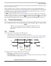
Clock control logic allows a selection of clock polarity and a choice of two fundamentally different
clocking protocols to accommodate most available synchronous serial peripheral devices. When the SPI
is configured as a master, the control bits in the HCKR select the appropriate clock rate, as well as the
desired clock polarity and phase format (see Figure 7-6).
The SS line allows individual selection of a slave SPI device; slave devices that are not selected do not
interfere with SPI bus activity (i.e., they keep their MISO output pin in the high-impedance state). When
the SHI is configured as an SPI master device, the SS line should be held high. If the SS line is driven low
when the SHI is in SPI Master mode, a bus error will be generated (the HCSR HBER bit will be set).
7.6 I
2
C Bus Characteristics
The I
2
C serial bus consists of two bi-directional lines, one for data signals (SDA) and one for clock signals
(SCL). Both the SDA and SCL lines must be connected to a positive supply voltage via a pull-up resistor.
NOTE
Within the I
2
C bus specifications, the standard mode (100 kHz clock rate)
and a fast mode (400 kHz clock rate) are defined. The SHI may operate in
both modes.
7.6.1 Overview
The I
2
C bus protocol must conform to the following rules:
• Data transfer may be initiated only when the bus is not busy.
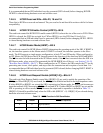
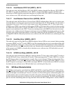
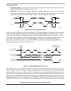
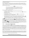
• During data transfer, the data line must remain stable whenever the clock line is high. Changes in
the data line when the clock line is high will be interpreted as control signals (see Figure 7-7).
Figure 7-7 I
2
C Bit Transfer
Accordingly, the I
2
C bus protocol defines the following events:
• Bus not busy—Both data and clock lines remain high.
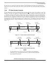
• Start data transfer—The start event is defined as a change in the state of the data line, from high
to low, while the clock is high (see Figure 7-8).
SDA
SCL
Data Line
Stable:
Data Valid
Change
of Data
Allowed
AA0422