


FX
3G
/FX
3U
/FX
3UC
PLC User's Manual - Positioning Control Edition
Built-in Positioning Functions
4 Before Programming
4.5 Setting of Various Items on PLC Side
B - 62
4.5.2 Setting of High-Speed Output Special Adapter
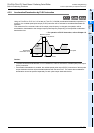
If a high-speed output special adapter (FX3U-2HSY-ADP) is used, the pulse output method can be selected
from "pulse train + direction" method and "forward/reverse rotation pulse train" method.
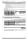
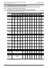
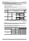
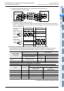
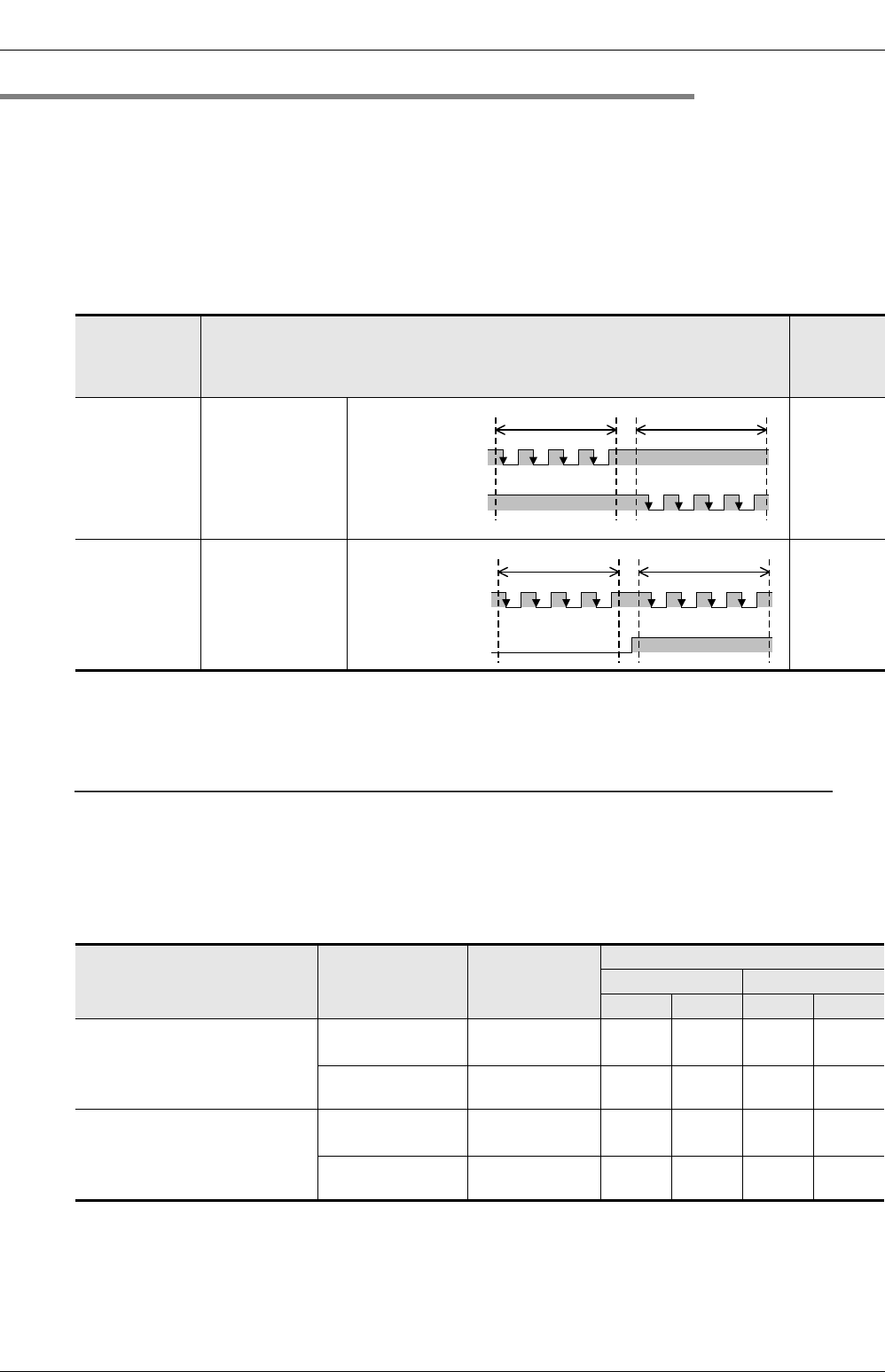
1. Setting of pulse output method
Using the pulse output method setting switch on the high-speed output special adapter (FX3U-2HSY-ADP),
set the pulse output method as shown in the following table.
The pulse output method setting should conform to the command pulse input method setting for the servo
amplifier (drive unit).
→ For details on the servo amplifier (drive unit), refer to the manual of the product used in your
system.
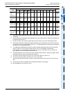
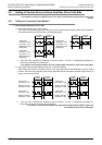
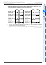
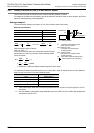
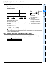
*1. "ON" and "OFF" represent the statuses of the PLC output. "H" and "L" respectively represent the
HIGH status and the LOW status of the waveform.
→ For details on the relation between the PLC output and the waveform, refer to
Subsection 4.6.1.
Caution:
Use the Output Form Setting Switch while the PLC is in STOP or while the power is OFF. Do not operate the
Output Form Setting Switch while a pulse train is being generated.
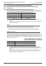
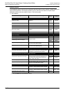
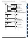
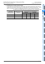
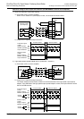
2. Setting of rotation direction signal for positioning instruction
If a high-speed output special adapter (FX3U-2HSY-ADP) is used, the rotation direction signal will be
assigned to each pulse output destination device as shown in the following table. Set the rotation direction
signal of the positioning instruction as shown in the following table:
Position of
pulse output
method setting
switch
Pulse output method
Logic of
command
pulse
FP
•
RP side
Forward rotation
pulse train (FP)
Reverse rotation
pulse train (RP)
Negative
logic
PLS
•
DIR side
Pulse train +
direction
Negative
logic
Position of pulse output
method setting switch of high-
speed output special adapter
Signal
Name of
positioning
instruction
Output number
1st adapter 2nd adapter
1st axis 2nd axis 3rd axis 4th axis
FP
•
RP side
Forward rotation
pulse train (FP)
Pulse output
destination:
Y000 Y001 Y002 Y003
Reverse rotation
pulse train (RP)
Rotation direction
signal
Y004 Y005 Y006 Y007
PLS
•
DIR side
Pulse train
Pulse output
destination:
Y000 Y001 Y002 Y003
Direction
Rotation direction
signal
Y004 Y005 Y006 Y007
OFF
Forward rotation
pulse train (FP)
Reverse rotation
pulse train (RP)
Forward rotation Reverse rotation
*
1
OFF*
1
H
L
H
L
OFF
Pulse train
Direction
Forward rotation Reverse rotation
H
L
H
L
*
1
ON*
1
*
1