


FX
3G
/FX
3U
/FX
3UC
PLC User's Manual - Positioning Control Edition
Built-in Positioning Functions
9 One-speed Interrupt constant quantity feed -DVIT Instruction
9.3 Function and Operation
B - 127
A
Common Items
B
Built-in
Positioning
Functions
Apx.
Example
Connection
9.3 Function and Operation
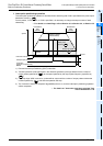
→ For details on the maximum speed, bias speed,acceleration time, and deceleration time, refer to
Subsection 4.2.5 to Subsection 4.2.8.
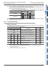
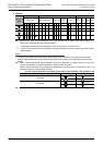
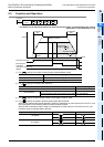
1) For , specify the number of output pulses (relative address value).
2) For , specify the output pulse frequency.
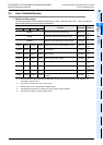
3) For , specify the pulse output number in the range of Y000 to Y003.
4) For , specify the rotation direction signal output device number.
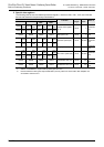
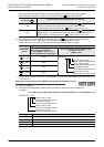
When a high-speed output special adapter is used as a destination for pulse output on a FX
3U PLC, use
the output shown in the following table for rotation direction signals.
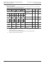
When a built-in transistor output is used as a destination for pulse output on a FX
3U/FX3UC PLC, use
transistor output for signals rotation direction.
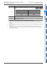
Setting range
16-bit operation -32,768 to +32,767 (excluding 0)
32-bit operation -999,999 to +999,999 (excluding 0)
Setting range
16-bit operation 10 to 32,767(Hz)
32-bit operation
When a high-speed output special adapter is used 10 to 200,000(Hz)
When a transistor output from the main unit is used 10 to 100,000(Hz)
High-speed output special adapter number Pulse output destination device Rotation direction output
1st adapter
= Y000
= Y004
= Y001
= Y005
2nd adapter
= Y002
= Y006
= Y003
= Y007
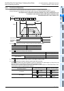
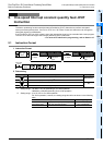
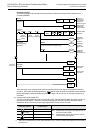
Command
input
FNC 151
DVIT
S
2
•
S
1
•
D
1
•
D
2
•
ON
Instruction execution
Interrupt input
Time
Speed
"Instruction
execution complete" flag
M8029
Maximum speed
Deceleration
time
Bias
speed
Acceleration
time
Output pulse
frequency
Number of output
pulses
S
1
•
S
2
•
S
1
S
2
D
1
D
2
D
1
D
2
D
1
D
2
D
1
D
2
D
1
D
2