


FX
3G
/FX
3U
/FX
3UC
PLC User's Manual - Positioning Control Edition
Common Items
2 Unit Connection
2.1 FX3U PLC
A - 9
A
Common Items
B
Built-in
Positioning
Functions
Apx.
Example
Connection
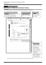
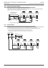
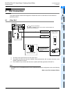
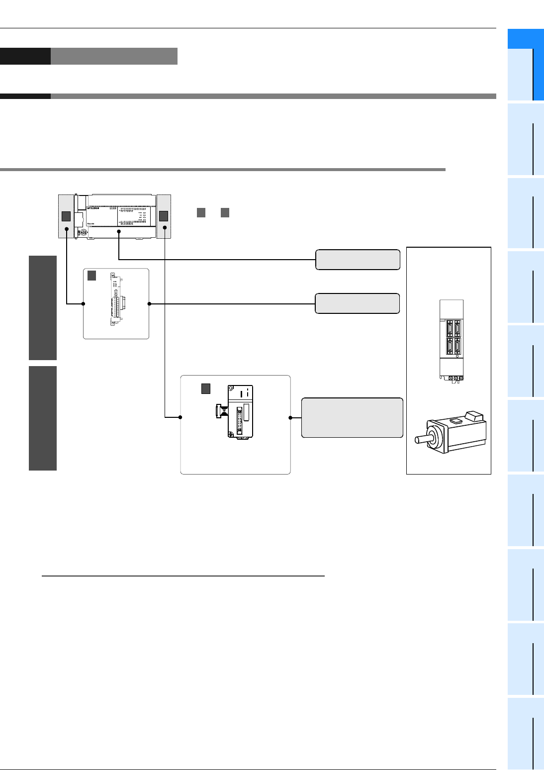
2. Unit Connection
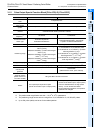
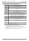
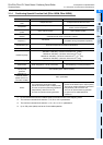
This chapter displays several block diagrams to illustrate the various combinations of units needed for
positioning control.
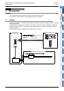
2.1 FX3U PLC
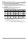
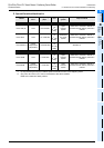
*1. The relay output type PLCs do not have pulse output.
*2. The product connects with the servo amplifier via the terminal block, MIL connector (20 pins), or the
SSCNET dedicated connector.
*3. FX
3U-20SSC-H only connects with the servo amplifier (MR-J3B) applicable to SSCNET III.
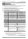
Note:
• For details on the connectable special function units/blocks and system configuration, refer to the following
manual.
→ Refer to the FX
3U Hardware Edition.
Up to 2 units can be
connected.
Servo motor or
Stepping motor
*3
European terminal
board
FX
3U
Series
A B
Special function block
Special function unit
- Terminal board (M3)
*2
- MIL connector (20-pin)
*2
- SSCNET dedicated
connector
*2
B and show the unit positions.
(For details of installation, refer to the manuals of special adapter and
special function units/blocks.)
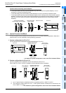
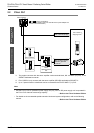
A
FX
3U
-2HSY-ADP
A
B
Up to 8 units can be
connected.
FX
2N
-10PG
f
B
f
A
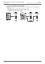
START
DOG
X1
X0
POWER
ERROR
FP
PGO
RP
CLR
Terminal block (M3)
(Transistor output)
*1