


FX
3G
/FX
3U
/FX
3UC
PLC User's Manual - Positioning Control Edition
Built-in Positioning Functions
4 Before Programming
4.8 Items To Be Observed When Using the Main Unit (Transistor Output)
B - 76
4.8 Items To Be Observed When Using the Main Unit (Transistor Output)
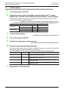
1. Pulse output destination devices
Use Y000, Y001, and Y002
*1
transistor outputs of the main unit for the pulse output destination devices.
Do not use the transistor output Y003 of the main unit for positioning instructions. If Y003 is used for a positioning
instruction, PLC failure may occur.
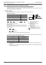
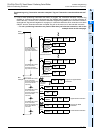
2. Pulse output method
Adjust the pulse output method of the transistor output of the main unit to conform with the command pulse
input method of the servo amplifier (drive unit).
If the pulse output method is not properly adjusted, the servo amplifier (drive unit) may not perform the
intended operation.
→ For details on the servo amplifier (drive unit), refer to the manual of the product used in your
system.
→ For details on the pulse output method of the main unit, refer to Subsection 4.6.1.
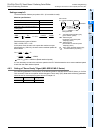
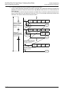
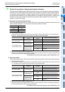
3. Output pulse frequency (including zero return speed)
If more than 100,000 Hz pulse is output from the transistor output terminal of the main unit to perform the
operation, it may cause PLC failure.
The output pulse frequency and the zero return speed should be equal to or less than the maximum frequency
of the servo amplifier (drive unit).
4. Load current
To use a positioning instruction for the transistor output Y000, Y001, or Y002
*1
of the main unit, adjust the
load current of the open collector transistor output to 10 to 100 mA (5 to 24V DC).
*1. Y002 is not available in 14-point and 24-point type FX
3G PLC.
4.9 Caution for Using the High-Speed Output Special Adapter
(FX3U-2HSY-ADP)
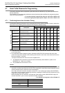
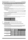
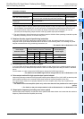
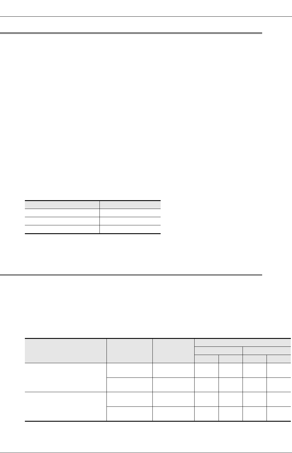
1. Output terminals to be used
If the high-speed output special adapter is connected, output numbers will be assigned in the same way as
the main unit as shown in the following table. Use the output terminals of one side (main unit side or high-
speed output special adapter side), and do not connect lines to the output terminals of the unused side.
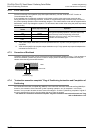
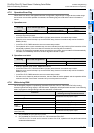
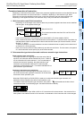
The outputs of the high-speed output special adapter and the main will operate as follows.
Assignment of output numbers
Item Description
Operation voltage range 5 to 24V DC
Operation current range 10 to 100mA
Output pulse frequency 100 kHz or less
Position of pulse output method
setting switch of high-speed
output special adapter
Signal
Name of
positioning
instruction
Output number
1st adapter 2nd adapter
1st axis 2nd axis 3rd axis 4th axis
FP
•
RP side
Forward rotation
pulse train (FP)
Pulse output
destination
Y000 Y001 Y002 Y003
Reverse rotation
pulse train (RP)
Rotation
direction signal
Y004 Y005 Y006 Y007
PLS
•
DIR side
Pulse train
Pulse output
destination
Y000 Y001 Y002 Y003
Direction
Rotation
direction signal
Y004 Y005 Y006 Y007