


FX
3G
/FX
3U
/FX
3UC
PLC User's Manual - Positioning Control Edition
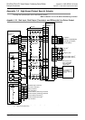
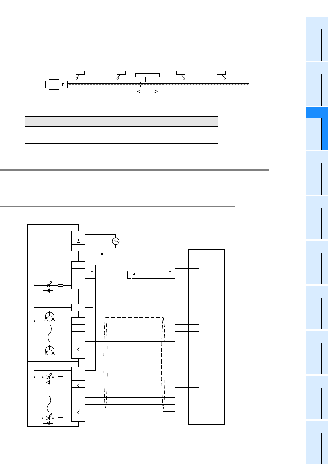
Example Connection
Appendix 1: MELSERVO-J3 Series
Appendix 1-3 Absolute Position Detection (Transistor Output)
Apx. - 7
A
Common Items
B
Built-in
Positioning
Functions
Apx.
Example
Connection
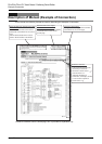
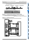
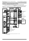
*3. To ensure safety, use the forward rotation limit switch and the reverse rotation limit switch on both sides: the PLC side and
the servo amplifier side. Note that the limit switches on the PLC side should be activated slightly earlier than the limit
switches on the servo amplifier side.
*4. To detect absolute positions, connect this line to the PLC.
*5. Set the pulse output form by pulse output form setting switch.
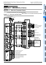
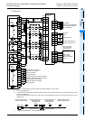
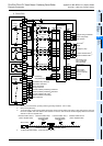
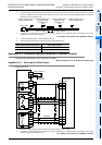
Appendix 1-3 Absolute Position Detection (Transistor Output)
To assign the inputs/outputs, refer to the following section.
→ Refer to Section 12.1 of "B. Built-in Positioning Function"
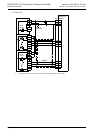
Appendix 1-3-1 Sink Input and Sink Output
1. FX3U/FX3G PLC
*1. Be sure to use the class-D grounding method (grounding resistance: 100
Ω
or less).
Pulse output method setting switch Pulse output method
FP
•
RP side Forward/reverse pulse train
PLS
•
DIRside Pulse train + direction
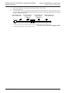
Reverse rotation limit 2
(Servo amplifier side)
Reverse rotation limit 1
(Programmable
controller side)
LSR
Forward rotation limit 2
(Servo amplifier side)
Forward rotation limit 1
(Programmable
controller side)
LSF
Reverse rotation Forward rotation
Servo motor
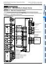
FX
3U
-32MT/ES
X000
24V
0V
S/S
N
L
100V to 240V AC
COM1
FX
2N
-16EYT
Y020
Y27
Y021
Y022
Y023
ABS(bit0)
ABS(bit1)
DOCOM
46
22
DICOM
20
ABST 25
ABSB
1
23
SD
Plate
CN1
SON 15
ABSR
18
ABSM
17
ABSB0
22
ABST 25
ABSB1
23
S/S
X020
FX
2N
-16EX-ES/UL
X031
X032
X033
X037
24V DC
Photo-
coupler
Photo-
coupler
Class-D
grounding
*1
Servo-ON
ABS transfer mode
ABS request
MR-J3
A
Series servo
amplifier
Send data ready