


FX
3G
/FX
3U
/FX
3UC
PLC User's Manual - Positioning Control Edition
Built-in Positioning Functions
4 Before Programming
4.6 Setting of Various Items on Servo Amplifier (Drive Unit) Side
B - 66
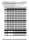
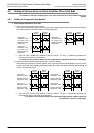
Reference: Image of PLC output and waveform (for MELSERVO-J3 Series servo amplifier)
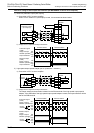
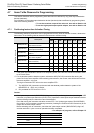
1) Base unit (transistor output (sink output))
a) Connection of PLC to servo amplifier
When a FX
3U Series PLC (sink output) is used, it is connected as shown below.
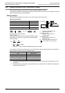
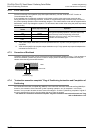
b) Image of PLC output and output waveform
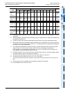
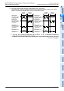
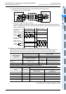
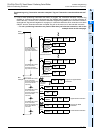
2) High-speed output special adapter (set to "pulse train + direction")
a) Connection of PLC to servo amplifier
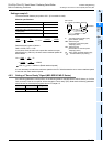
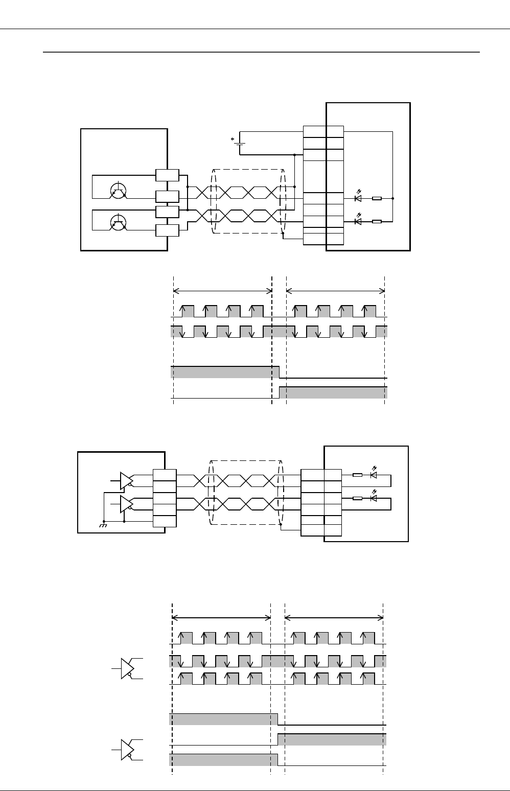
b) Image of PLC output and output waveform
The output waveform shown below is based on the SGA terminal of the high-speed output special
adapter. If the SGB side of the high-speed output special adapter is used, the output waveform will be
that of the SGB terminal.
PP 10
DOCOM
46
OPC 12
NP 35
24V DC
Pulse train
Direction
SD
Plate
COM1
Y000
Y004
MR-J3
A servo
amplifier
FX
3U
-32MT/ES
(Transistor output
(sink output))
COM2
Pulse train signal
(Y000)
Direction output
(Y004)
Image of output
ON/OFF operation
Output waveform
Image of output
ON/OFF operation
Output waveform
ON
OFF
High
Low
Forward rotation Reverse rotation
ON
OFF
High
Low
Y0/2+
FX
3U
-2HSY-ADP
Y0/2-
SGA
Y4/6+
Y4/6-
Equivalent
to AM26C31
SGA
Pulse train
Direction
SD
Plate
MR-J3
A servo
amplifier
NP 35
PP 10
PG 11
NG 36
Pulse train signal
(Y000)
Direction output
(Y004)
Image of output
ON/OFF operation
Output
waveform
Forward rotation Reverse rotation
ON
OFF
High
Low
High
Low
ON
OFF
High
Low
High
Low
Image of output
ON/OFF operation
Output
waveform
+
-
+
-