


FX
3G
/FX
3U
/FX
3UC
PLC User's Manual - Positioning Control Edition
Built-in Positioning Functions
7 Absolute Position Detection System (Absolute Current Value Read)-ABS Instruction
7.2 List of Related Devices
B - 108
7.2 List of Related Devices
→ For details on the related devices, refer to Section 4.1 to Section 4.4.
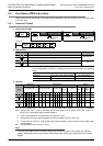
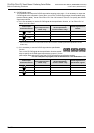
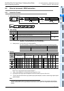
1. Special auxiliary relays
The following table shows the related special auxiliary relays.
Note that Y000, Y001, Y002, and Y003 are devices that determine the pulse output destinations.
→ For details on PLSY (FNC57), PWM (FNC58), and PLSR (FNC59) instructions, refer to the
programming manual.
*1. Y002 is not available in 14-point and 24-point type FX3G PLC.
*2. Devices related to Y003 (pulse output destination) are only valid if two FX
3U-2HSY-ADP adapters are
connected to the FX
3U PLC.
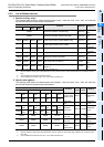
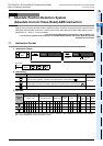
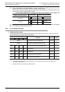
2. Special data registers
The following table shows the related special data registers. Note that Y000, Y001, Y002, and Y003 are
devices that determine the pulse output destinations.
*1. Y002 is not available in 14-point and 24-point type FX3G PLC.
*2. Devices related to Y003 (pulse output destination) are only valid if two FX
3U-2HSY-ADP adapters are
connected to the FX
3U PLC.
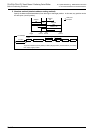
7.3 Function and Operation
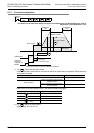
Connect an MR-H, MR-J2(S), or MR-J3 servo motor (with absolute position detection function) manufactured
by Mitsubishi to your system, and use this instruction to read out the absolute position (ABS) data. The data
will be converted into a pulse value before being read out.
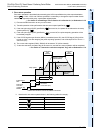
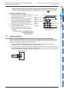
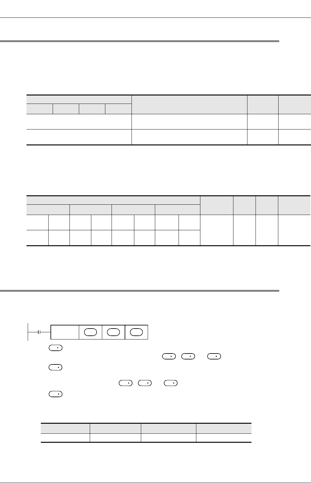
1) For , specify the first number of the device that inputs the absolute position (ABS) data from the
servo amplifier. Number of occupied points: 3 ( , +1, +2)
2) For , specify the first number of the device that outputs the absolute position (ABS) data control
signal to the servo amplifier. Be sure to use transistor outputs for the PLC outputs.
Number of occupied points: 3 ( , +1, +2)
3) For , specify the absolute position (ABS) data (32-bit value) storage device number to store the
data read out from the servo amplifier. Handle the absolute position (ABS) data as follows:
- To use the built-in pulse output function, be sure to specify the following current value registers for the
read-out ABS data:
*1. Y002 is not available in 14-point and 24-point type FX3G PLC.
*2. Devices related to Y003 (pulse output destination) are only valid if two FX
3U-2HSY-ADP adapters are
connected to the FX
3U PLC.
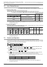
Device number
Function Attribute Refer to
Y000 Y001
Y002
*1
Y003
*2
M8029 "Instruction execution complete" flag Read only
Subsection
4.4.2
M8329 "Instruction execution abnormal end" flag Read only
Subsection
4.4.2
Device number
Function
Data
length
Initial
value
Refer to
Y000 Y001
Y002
*1
Y003
*2
D8340
Low-
order
D8350
Low-
order
D8360
Low-
order
D8370
Low-
order
Current
value
register
(PLS)
32-bit 0
Subsection
4.4.1
D8341
High-
order
D8351
High-
order
D8361
High-
order
D8371
High-
order
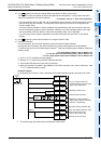
Y000 Y001
Y002
*1
Y003
*2
D8341,D8340 D8351,D8350 D8361,D8360 D8371, D8370
Command
input
FNC 155
DABS
S
•
D
1
•
D
2
•
S
S
S
S
D
1
D
1
D
1
D
1
D
2