


FX
3G
/FX
3U
/FX
3UC
PLC User's Manual - Positioning Control Edition
Built-in Positioning Functions
7 Absolute Position Detection System (Absolute Current Value Read)-ABS Instruction
7.5 Important Points
B - 110
7.5 Important Points
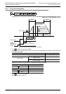
• Set the timing sequence for powering on your system so that the power of the PLC is turned on after the
power of the servo amplifier, or that power is turned on at the same time.
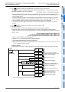
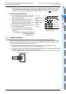
• Leave the drive contact of the DABS (FNC155) instruction ON after reading the ABS value. If the
instruction activation contact is turned off at the completion of ABS data reading, the servo-ON (SON)
signal will be turned off, and the operation will not be performed.
• If the instruction activation contact is turned off during data reading, data reading will be stopped.
• This instruction is for 32-bit data only. Be sure to input this instruction as the DABS instruction.
• Observe the following items to use the FX
2N-1PG(-E) or FX2N-10PG:
- ABS data will be converted into a pulse value before being read out. For this reason, be sure to specify
"motor system" when setting the parameters (BFM #3) for the FX
2N-1PG(-E).
- When writing ABS data to the FX
2N-10PG, be sure to use the current value register (BFM #40, BFM
#39) to store the converted pulse data.
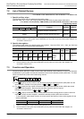
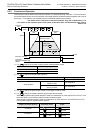
• Even if data-communication with the servo amplifier is not performed properly, no error will be detected.
For this reason, it is necessary to monitor the handshaking operation using the time-out error detection
timer.
→ For the example programs, refer to Section 12.5.
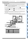
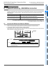
• Set the servo motor rotation direction as described below when using the ABS instruction. Note that the
sign (plus or minus) may be different between the current value controlled by the PLC and the current
value existing in the servo amplifier after the current value is read by the ABS instruction if another
direction is set.In the MR-J2--A and MR-H--A, the setting "Forward rotation (CCW) when forward
rotation pulses are input, and reverse rotation (CW) when reverse rotation pulses are input" cannot be
changed.
- When using the positioning function built in the FX
3G, FX3U and FX3UC PLC
Set the servo amplifier rotation direction to "Forward rotation (CCW) when forward rotation pulses are
input, and reverse rotation (CW) when reverse rotation pulses are input".
→ For details, refer to the Servo amplifier manual.
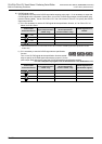
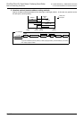
- When using the FX
2N-1PT or FX2N-10PG with the FX3U or FX3UC PLC
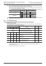
Achieve the following relationship for the rotation direction setting between the FX
2N-1PG or FX2N-
10PG and the servo amplifier.
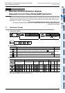
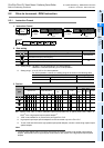
Setting in FX2N-1PG(-E)/FX2N-10PG Setting in servo amplifier
Current value is increased by forward
rotation pulses.
Servo amplifier rotates forward (CCW) when forward
rotation pulses are input.
Servo amplifier rotates backward (CW) when
reverse rotation pulses are input.
Current value is decreased by forward
rotation pulses.
Servo amplifier rotates forward (CW) when forward
rotation pulses are input.
Servo amplifier rotates backward (CCW) when
reverse rotation pulses are input.