


FX
3G
/FX
3U
/FX
3UC
PLC User's Manual - Positioning Control Edition
Built-in Positioning Functions
12 Examples of Programs
12.1 Input/Output Assignment
B - 154
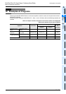
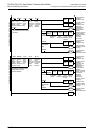
12.1 Input/Output Assignment
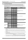
The programs shown in this chapter use 1 axis for Y000 (pulse output destination device). If other pulse
output destination device are used, change various device numbers when reading the description.
Note that Y003 (pulse output destination device) can be used only if two FX
3U-2HSY-ADP adapters are
connected to the FX
3U PLC.
*1. To use the "forward rotation pulse train" signal and "reverse rotation pulse train" signal of a FX
3U-
2HSY-ADP, change the name of this signal to "forward rotation pulse train" signal when reading the
description.
*2. To use the "forward rotation pulse train" signal and "reverse rotation pulse train" signal of a FX
3U-
2HSY-ADP, change the name of this signal to "reverse rotation pulse train" signal when reading the
description.
*3. If an FX
3UC PLC below Ver.2.20 is used, exchange the direction signal output number with the CLEAR
signal output number.
*4. If the absolute position detection system is used, and if the DSZR instruction and ZRN instruction are
not used for the first zero return, this signal is not needed. To use the absolute position detection
system, refer to the following chapter and manual.
→ Refer to Chapter 7 and the manual of your servo amplifier.
*5. To use the ZRN instruction for zero return, assign the input number of the near-point signal (DOG) to
the zero-phase signal. This is needed since the ZRN instruction will not use the zero-phase signal.
Signal
Input/output number
Connected to
Y000 Y001 Y002 Y003
Pulse train
*1
(pulse output destination)
Y000 Y001 Y002 Y003
Connected to MELSERVO Series
servo amplifier.
Direction
*2, *3
(rotation direction signal)
Y004 Y005 Y006 Y007
CLEAR signal
*3, *4
Y020 Y024 Y030 Y034
Zero-phase signal
*4, *5
X004 X005 X006 X007
"Servo ready" signal
*6
X014 X015 X016 X017
Immediate stop command X020 X040 X050 X070
Connected to external switches.
Zero return command X021 X041 X051 X071
Jog (+) command X022 X042 X052 X072
Jog (-) command X023 X043 X053 X073
Forward rotation positioning
command
X024 X044 X054 X074
Reverse rotation positioning
command
X025 X045 X055 X075
Stop command X030 X034 X060 X064
Near-point signal (DOG)
*4, *5
X010 X011 X012 X013
Connected to sensors and limit switches.
Interrupt signal X000 X001 X002 X003
Forward rotation limit (LSF)
*7
X026 X046 X056 X076
Reverse rotation limit (LSR)
*7
X027 X047 X057 X077
To use absolute
position detection
system
ABS(bit0) X031 X035 X061 X065
Connected to Mitsubishi MELSERVO Series
servo amplifier
(MR-J2,MR-J2S, MR-J3, MR-H)
ABS(bit1) X032 X036 X062 X066
"Send data ready"
signal
X033 X037 X063 X067
Servo-ON signal Y021 Y025 Y031 Y035
"ABS data transfer
mode" signal
Y022 Y026 Y032 Y036
"ABS data
request" signal
Y023 Y027 Y033 Y037