


3 Connection of Input/Output Lines and Tightening
B - 32
FX
3G
/FX
3U
/FX
3UC
PLC User's Manual - Positioning Control Edition
Built-in Positioning Functions
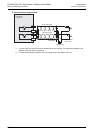
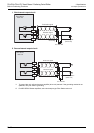
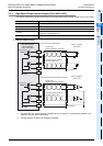
3. Connection of Input/Output Lines and Tightening Torques
This chapter describes how to connect the input/output lines and the terminal tightening torques.
WIRING PRECAUTIONS
• Make sure to cut off all phases of the power supply externally before attempting installation or wiring work.
Failure to do so may cause electric shock or damage to the product.
• Make sure to attach the terminal cover, offered as an accessory, before turning on the power or initiating operation
after installation or wiring work.
Failure to do so may cause electric shock.
WIRING PRECAUTIONS
• Connect the AC power supply to the dedicated terminals specified in the manual of the PLC main unit.
If an AC power supply is connected to a DC input/output terminal or DC power supply terminal, the PLC will burn
out.
• Connect the DC power supply to the dedicated terminals specified in the manual of the PLC main unit.
If an AC power supply is connected to a DC input/output terminal or DC power supply terminal, the PLC will burn
out.
• Do not wire vacant terminals externally.
Doing so may damage the product.
• Perform class D grounding (grounding resistance: 100Ω or less) to the grounding terminal on the FX
3U/FX3G PLC
main unit with a wire 2 mm
2
or thicker.
Do not use common grounding with heavy electrical systems (refer to the manual of the PLC main unit).
• Perform class D grounding (grounding resistance: 100Ω or less) to the grounding terminal on the main unit.
Do not use common grounding with heavy electrical systems.
• When drilling screw holes or wiring, make sure cutting or wire debris does not enter the ventilation slits.
Failure to do so may cause fire, equipment failures or malfunctions.
• Install module so that excessive force will not be applied to I/O connectors.
Failure to do so may result in wire damage/breakage or PLC failure.
• Connect input/output cables securely to their designated connectors.
Loose connections may cause malfunctions.
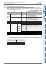
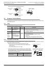
• Make sure to properly wire the FX
3U/FX3G Series main unit and FX0N/FX2N Series extension equipment in
accordance with the following precautions.
Failure to do so may cause electric shock, a short-circuit, wire breakage, or damage to the product.
- The disposal size of the cable end should follow the dimensions described in this manual.
- Tightening torque should be between 0.5 and 0.8 N
•
m.
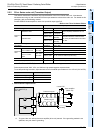
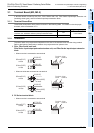
• Make sure to properly wire to the European terminal board in accordance with the following precautions.
Failure to do so may cause electric shock, a short-circuit, wire breakage, or damage to the product.
- The disposal size of the cable end should follow the dimensions described in this manual.
- Tightening torque should be between 0.22 and 0.25 N
•
m.
- Twist the end of strand wire and make sure that there are no loose wires.
- Do not solder-plate the electric wire ends.
- Do not connect more than the specified number of wires or electric wires of unspecified size.
- Affix the electric wires so that neither the terminal block nor the connected parts are directly stressed.
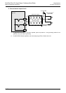
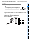
• Make sure to properly wire to the FX Series terminal blocks in accordance with the following precautions.
Failure to do so may cause electric shock, a short-circuit, wire breakage, or damage to the product.
- The disposal size of the cable end should follow the dimensions described in this manual.
- Tightening torque should be between 0.5 and 0.8 N
•
m.