


FX
3G
/FX
3U
/FX
3UC
PLC User's Manual - Positioning Control Edition
Built-in Positioning Functions
6 Mechanical Zero Return (DSZR/ZRN Instruction)
6.2 DOG Search Zero Return (DSZR Instruction)
B - 98
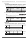
6.2.4 Important Points
→ For important programming points, refer to Section 4.7.
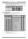
• If an input (X000 to X017)
*1
from the main unit is used for the near-point signal (DOG) , the rear end
of the near-point signal (DOG) will be monitored (detected) at 1ms intervals (interruption).
Under the following condition, however, monitoring (detection) of the near-point signal (DOG) rear end will
be affected by the input time constant or the scan time of the sequence program:
- An input number of X020 or below or other device (auxiliary relay, etc.) is specified.
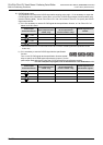
*1. Specify X000 to X007 for FX3U-16M, FX3UC-16M.
Specify X000 to X007 for FX3G PLC (main unit).
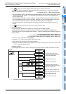
• Properly set the DOG so that the near-point signal (DOG) can be kept at the ON status until the speed is
reduced to the creep speed.
This instruction will start speed reduction at the front end of the DOG, and will stop the operation at the rear
end of the DOG or at detection of the first zero-phase signal after passing the rear end of the DOG.
The current value register will then be cleared (reset to "0").
If the speed is not reduced to the creep speed before detecting the rear end of the DOG, the operation may
not be stopped at the specified position.
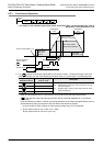
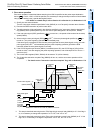
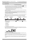
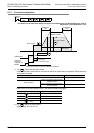
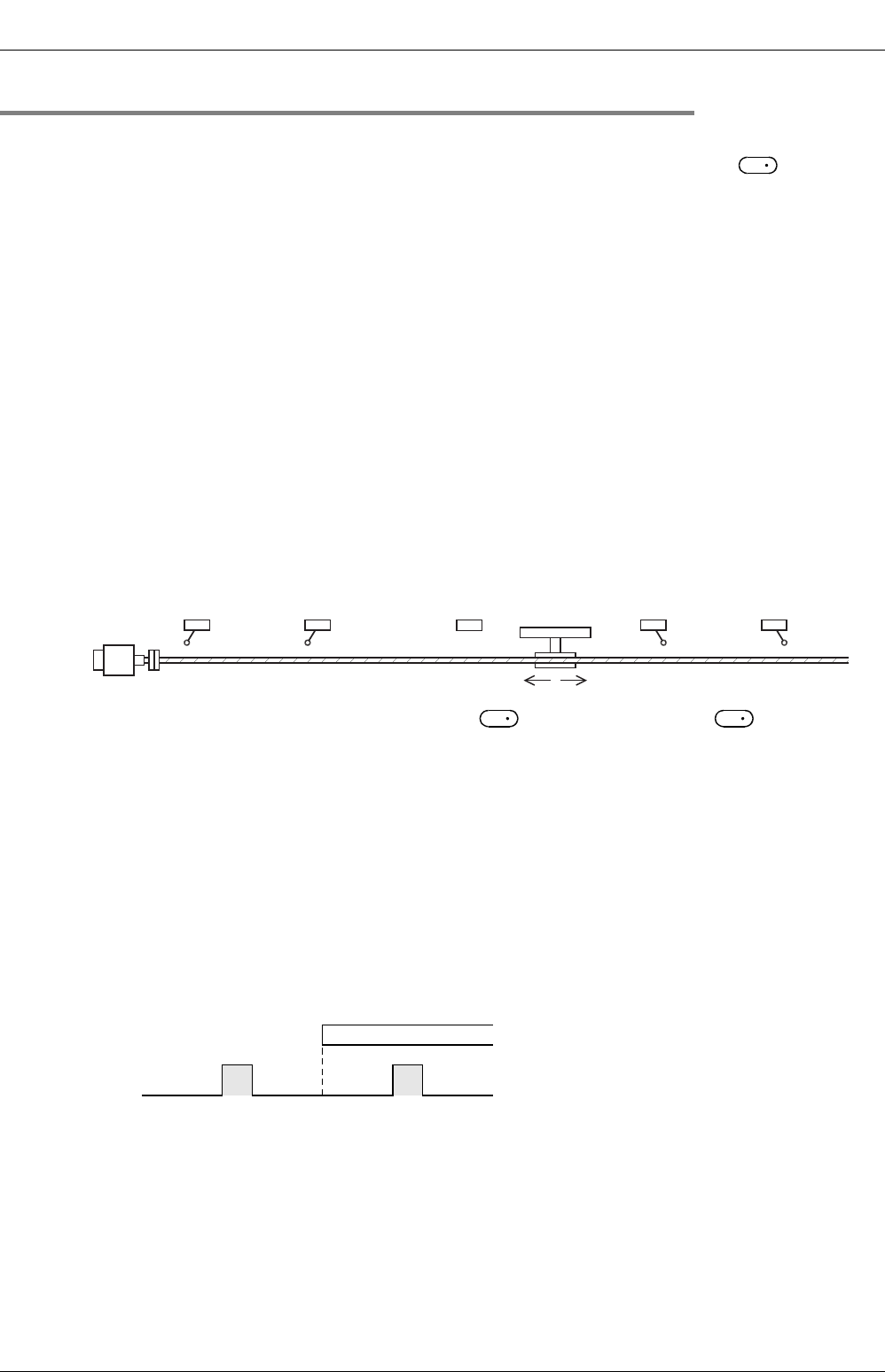
• Use the near-point signal (DOG) between the reverse rotation limit 1 (LSR) and the forward rotation limit 1
(LSF).
The intended operation may not be performed if the relationship among the near-point signal (DOG),
reverse rotation limit 1 (LSR) and forward rotation limit 1 (LSF) is not as shown in the figure below.
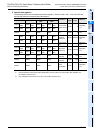
• The input device specified for the near-point signal or the zero-phase signal cannot be used
for the following items:
- High-speed counter
- Input interruption
- Pulse catch
- SPD instruction
- DVIT instruction
*2
- ZRN instruction
*2. O
nly available for FX3U and FX3UC PLCs.
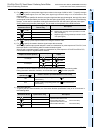
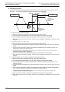
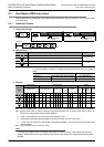
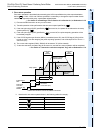
• Since the zero-phase signal of the servo motor is used, adjust the relation between the rear end of the
DOG and the zero-phase signal as shown in the following figure. If fine adjustment of the origin position is
needed, adjust the position of the near-point signal (DOG).
• The creep speed should be slow enough.
The zero return instruction will not decelerate at the stop point. Therefore, if the creep speed is not slow
enough, the operation may not stop at the specified position due to inertia.
• If an operand is changed during instruction execution, the change will be ignored and the operation will not
be affected. To change the operation, turn off the command contact of the instruction, and then turn it on
again.
• If the instruction activation contact is turned off during the zero return operation, the speed will decelerate
and the operation will stop. In this case, the "Instruction execution complete" flag (M8029) will not be
turned on.
S
1
Reverse rotation limit 2
(Servo amplifier side)
Reverse rotation limit 1
(Programmable
controller side)
LSR
Forward rotation limit 2
(Servo amplifier side)
Forward rotation limit 1
(Programmable
controller side)
LSF
Reverse rotation Forward rotation
Servo motor
DOG
S
1
S
2
DOG
Rear end
Zero-phase signal