


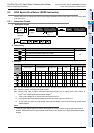

FX
3G
/FX
3U
/FX
3UC
PLC User's Manual - Positioning Control Edition
Built-in Positioning Functions
5 Operation Test
5.1 Test Procedure
B - 85
A
Common Items
B
Built-in
Positioning
Functions
Apx.
Example
Connection
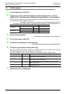
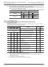
2. Stop of operation
Turn off the reverse rotation (JOG-) switch (X013) to stop the operation in the reverse rotation direction.
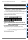
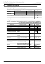
1) LED indicator lamp check
Check the LED indicator lamps of the PLC or the display module to check whether or not the outputs are
turned on. The status of each output should be as shown in the following table:
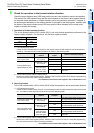
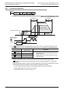
2) Current value register (D8341, D8340) check
Monitor the current value register (D8341, D8340) of the FX
3U/FX3UC/FX3G PLC using the programming
tool, and confirm that the value is not being decreased.
→ For details on the current value register, refer to Subsection 4.4.1.
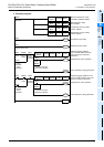
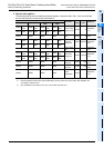
11 Check the operation of the reverse rotation limit switch.
During operation in the reverse rotation direction (at step 10), turn off the reverse rotation limit
switch 1 (X011), and confirm that the operation in the reverse rotation direction is stopped.
The LED indicator lamps and the current value register (D8341, D8340) will enter the same
statuses as the stop statuses described in step 10.
In addition, the "Instruction execution abnormal end" flag (M8329) will turn on.
→ For details on the current value register, refer to Subsection 4.4.1.
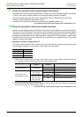
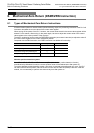
Pulse output
method
LED lamp
of output
Status of LED lamp (output)
If transistor outputs of main
unit are used
"Pulse train + direc-
tion" method
Y000
The LED indicator lamp (turned on and
off at high speed) will be turned off.
Y004 Kept OFF.
If high-speed output
special adapter is used
"Pulse train + direc-
tion" method
Y0/2
The LED indicator lamp (turned on and
off at high speed) will be turned off.
Y4/6 Kept OFF.
Forward rotation
pulse train (FP)
Reverse rotation
pulse train (RP)
Y0/2 Kept OFF.
Y4/6
The LED indicator lamp (turned on and
off at high speed) will be turned off.