


1 Outline
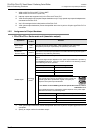
1.5 Assignment of Input/Output Numbers
B - 12
FX
3G
/FX
3U
/FX
3UC
PLC User's Manual - Positioning Control Edition
Built-in Positioning Functions
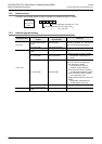
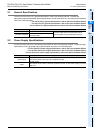
*1. X000 to X007 for FX3U-16M,
FX
3UC
-16M
.
X000 to X007 for FX3G PLC (main unit).
*2. Interrupt outputs are supported only in the FX
3U and FX3UC PLC.
*3. Y003 can be specified as the pulse output destination only if 2 high-speed output special adapters are
connected to the FX
3U PLC.
*4. Ver.2.20 is assigned to the initial product of the FX
3U PLC.
*5. Y002 (pulse output destination) cannot be specified when the 14-point or 24-point type FX
3G PLC is
connected.
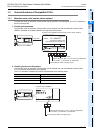
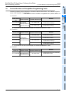
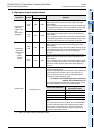
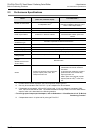
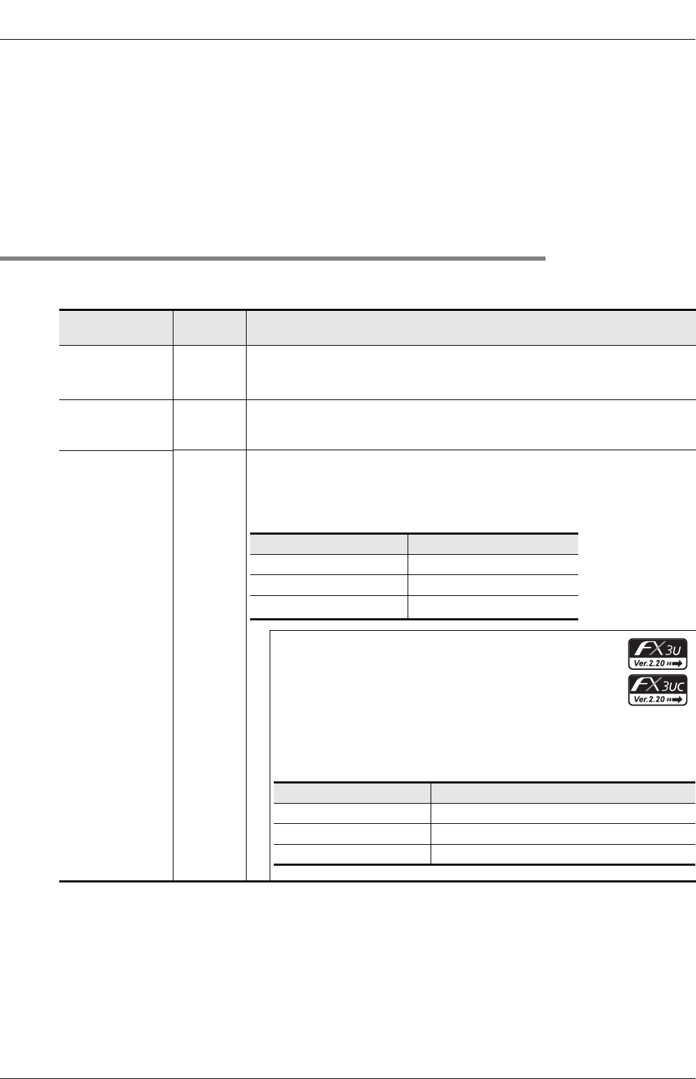
1.5.2 Assignment of Output Numbers
1. FX3G/FX3U/FX3UC Series main unit (transistor output)
*1. Y002 (pulse output destination) cannot be specified when the 14-point or 24-point type FX3G PLC is
connected.
*2. Specify an output number for transistor output.
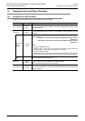
Application
Output
number
Remarks
Pulse train signal
(Pulse output
destination)
Y000
Y001
Y002
*1
Connect a line to the output (Y000 - Y002) specified for the pulse output
designation (this output is specified by the positioning instruction).
Direction signal
(Rotational
direction signal)
All output
points
*2
Connect a line to any output.
Connect a line to the output specified for the rotation direction signal (this signal is
specified by the positioning instruction).
CLEAR signal
All output
points
*2
Connect a line if it is necessary to use DSZR/ZRN instruction to output the CLEAR
signal.
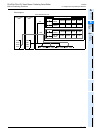
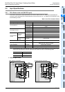
The CLEAR signal output depends on the pulse output destination specified by
the DSZR/ZRN instruction. If the PLC version is later than the following number,
the CLEAR signal can be specified.
FX
3U/FX3UC PLC (transistor output) Ver. 2.20 or later:
If the CLEAR signal device specification function is used, the
CLEAR signal device specification register can specify an
output for each pulse output destination.
→ For details on the CLEAR signal device specification method, refer to
Subsection 4.3.4.
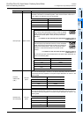
The CLEAR signal device specification register depends on the pulse output
destination as shown in the following table:
Pulse output destination CLEAR signal
Y000 Y004
Y001 Y005
Y002
*1
Y006
Pulse output destination CLEAR signal device specification register
Y000 D8464
Y001 D8465
Y002 D8466