


FX
3G
/FX
3U
/FX
3UC
PLC User's Manual - Positioning Control Edition
Built-in Positioning Functions
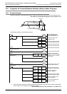
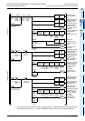
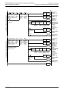
12 Examples of Programs
12.1 Input/Output Assignment
B - 155
A
Common Items
B
Built-in
Positioning
Functions
Apx.
Example
Connection
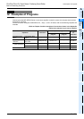
*6. To use pin 3 of the CN1 connector of the MR-CA servo amplifier for the "servo ready" signal, set
parameter 21 as follows:
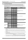
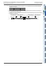
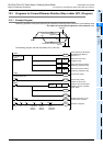
*7.
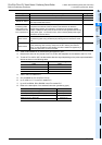
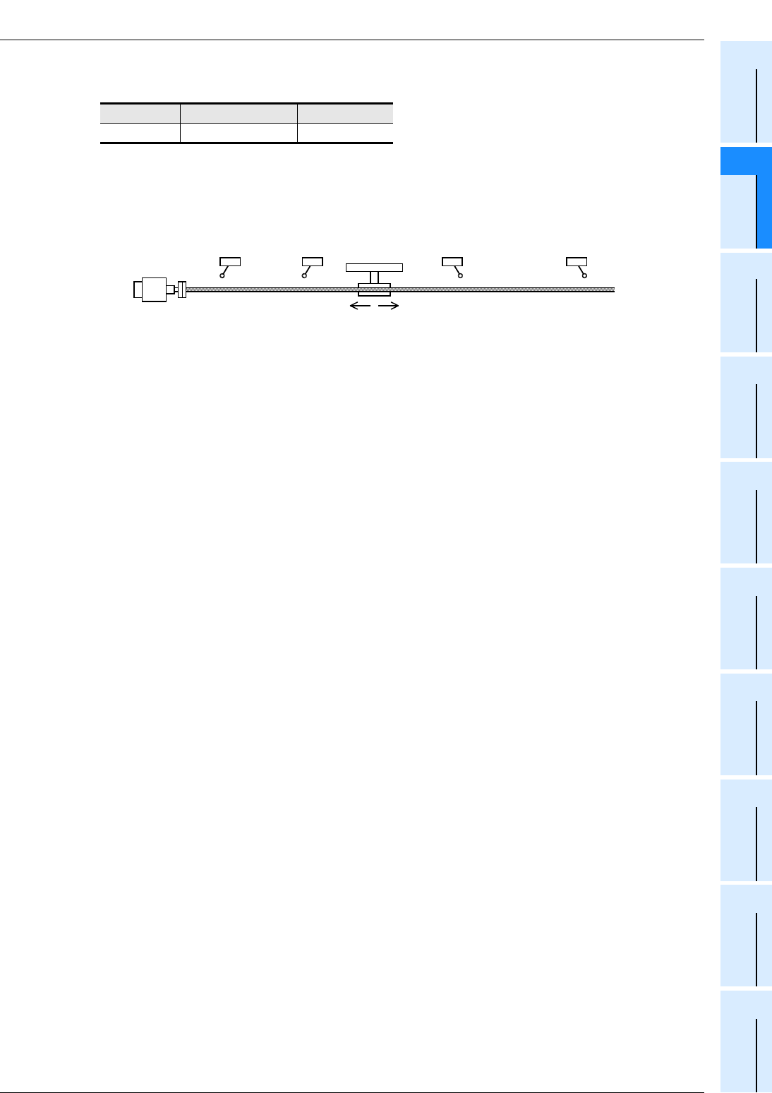
To ensure safety, use a forward rotation limit switch and reverse rotation limit switch on both sides: the
PLC side and the servo amplifier side.
Note that the limit switches on the PLC side should be activated slightly earlier than the limit switches
on the servo amplifier side.
Series Parameter number Setting value
MR-C 21 020
Reverse rotation limit 2
(Servo amplifier side)
Reverse rotation limit 1
(Programmable controller side)
Forward rotation limit 2
(Servo amplifier side)
Forward rotation limit 1
(Programmable controller side)
Reverse rotation Forward rotation
Servo motor
LSFLSR