FX
3G
/FX
3U
/FX
3UC
PLC User's Manual - Positioning Control Edition
Built-in Positioning Functions
4 Before Programming
4.6 Setting of Various Items on Servo Amplifier (Drive Unit) Side
B - 65
A
Common Items
B
Built-in
Positioning
Functions
Apx.
Example
Connection
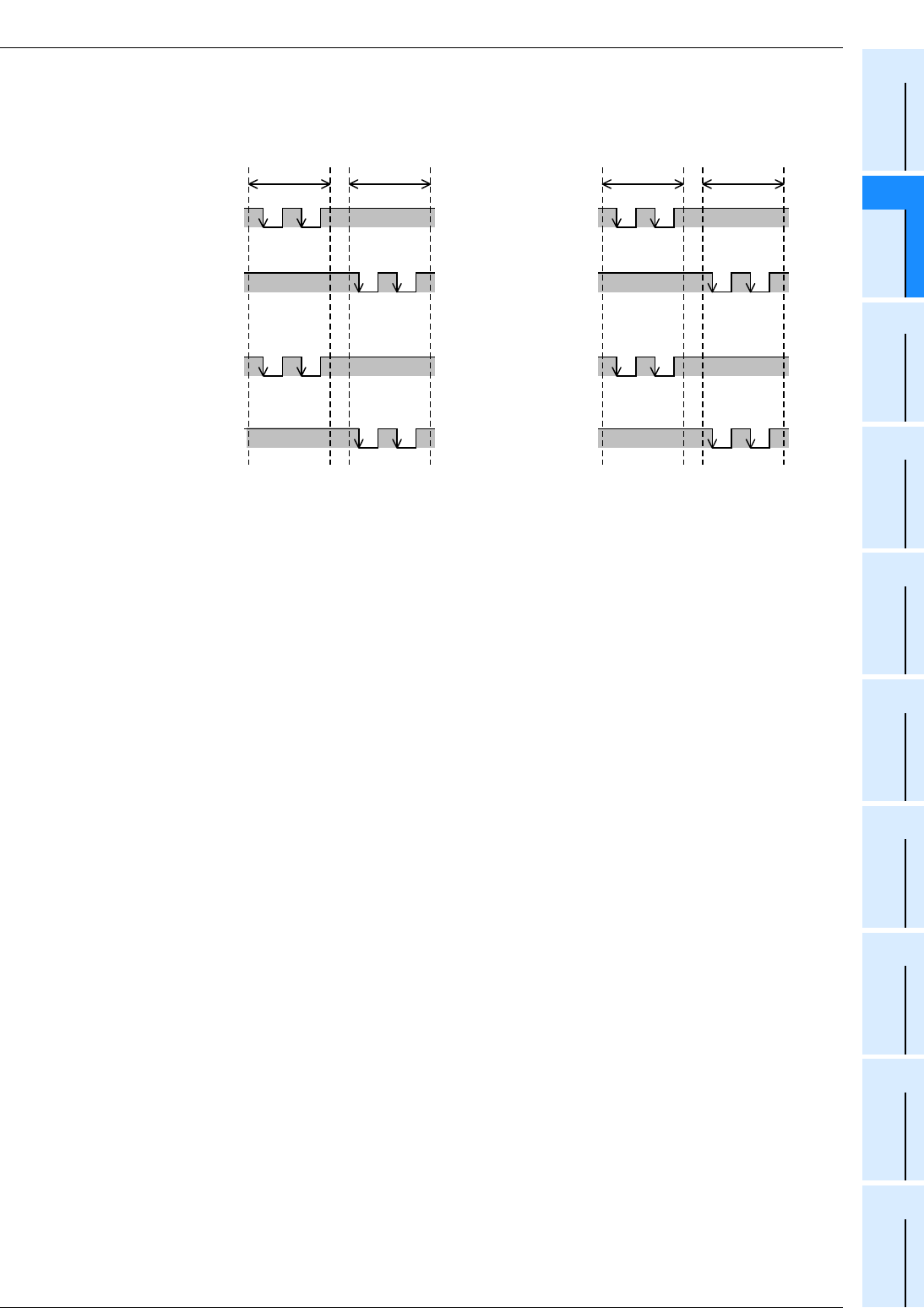
3) High-speed output special adapter (Forward/Reverse Pulse Train setting)
When setting the Output Form Setting Switch of the high speed output special adapter to the "FP
•
RP"
position, the pulse output signals will be as shown in the following figure.
*1. "ON" and "OFF" represent the statuses of the PLC output. "H" and "L" respectively represent the
HIGH status and the LOW status of the waveform.
→ For details on the relation between high-speed output special adapter output and the waveform,
refer to the next pages.
H
L
H
L
H
L
H
L
OFF *
1
OFF *
1
OFF *
1
OFF *
1
Forward
rotation
Reverse
rotation
Forward
rotation
Reverse
rotation
OFF *
1
H
L
H
L
H
L
H
L
OFF *
1
OFF *
1
OFF *
1
Pulse output
destination: Y002
(Forward rotation
pulse train)
Pulse output
destination: Y006
(Reverse rotation
pulse train)
Pulse output
destination: Y003
(Forward rotation
pulse train)
Pulse output
destination: Y007
(Reverse rotation
pulse train)
Pulse output
destination: Y001
(Forward rotation
pulse train)
Pulse output
destination: Y005
(Reverse rotation
pulse train)
Pulse output
destination: Y000
(Forward rotation
pulse train)
Pulse output
destination: Y004
(Reverse rotation
pulse train)


