


FX
3G
/FX
3U
/FX
3UC
PLC User's Manual - Positioning Control Edition
Built-in Positioning Functions
4 Before Programming
4.10 Format and Execution of Applied Instruction
B - 78
4.10 Format and Execution of Applied Instruction
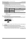
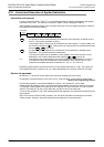
Instruction and operand:
- Function numbers (FNC00 - FNC) and symbols (mnemonic codes) are assigned to the applied
instructions of the PLC. For example, a symbol of "SMOV" (shift) is assigned to FNC13.
- Some applied instructions consist of the instruction area only, but many applied instructions consist of
the instruction area and the operand.
: An operand that will not be affected by the execution of the instruction is referred to as a
source. This symbol represents a source.
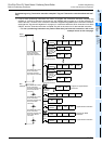
If the operand device number can be modified by an index register, "•" will be added, and
the S will be modified to . If there are two or more sources, the modified sources will
become , , and so on.
: An operand that will be affected by the execution of the instruction is referred to as a
destination. This symbol represents a destination.
If the device numbers can be indexed by index registers, and if there are two or more
destinations, the modified destinations will become , , and so on.
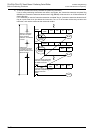
m, n : The operands not corresponding to source and destination are indicated as "m" and "n".
If the device number can be indexed by index registers, and if there are two or more
operands, the modified operands will become m1
•
, m2
•
, n1
•
, n2
•
, and so on.
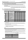
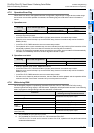
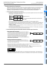
- Regarding program steps, the instruction area for each applied instruction is 1 step. The operand of
each applied instruction, however, has 2 or 4 steps depending on the number of bits (16 or 32 bits).
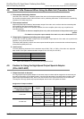
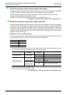
Devices for operands:
- Bit devices X, Y, M, and S can be used for the operands, depending on the function.
- Combination of these bit devices, such as KnX, KnY, KnM, and KnS, can be used for numeric data.
→ Refer to the programming manual.
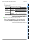
- Current value registers, such as data registers D, timers T, and counters C, can be used.
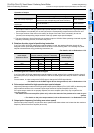
- A data register D consists of 16 bit. Two consecutive data registers (2 points) are used for 32-bit data.
For example, if data register D0 is specified for the operand of a 32-bit instruction, D1 and D0 will be
used for 32-bit data (D1 for the 16 high-order bits, and D0 for the 16 low-order bits).
If current value registers T and C are used as general data registers, they will behave the same way as
data registers.
Each 32-bit counter (C200 to C255), however, can use 32-bit data without combining two counters.
These counters, however, cannot be specified as the operands of 16-bit instructions.
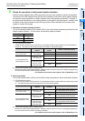
Command
input
FNC158
DRVI
S
1
•
S
2
•
D
1
•
D
2
•
S
S
S
1
S
2
D
D
1
D
2