


1 Outline
1.5 Assignment of Input/Output Numbers
B - 13
FX
3G
/FX
3U
/FX
3UC
PLC User's Manual - Positioning Control Edition
Built-in Positioning Functions
A
Common Items
B
Built-in
Positioning
Functions
Apx.
Example
Connection
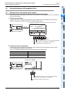
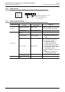
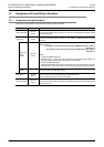
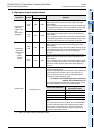
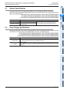
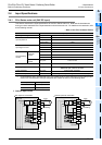
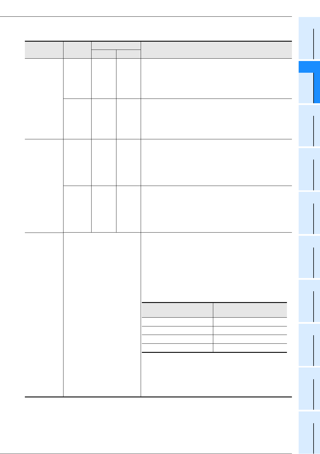
2. High-speed output special adapter
*1. Specify an output number for transistor output.
Application Terminal
Output number
Remarks
1st 2nd
Pulse train sig-
nal/forward
rotation pulse
train
(pulse output
destination)
Y0/2+
Y0/2-
Y000 Y002
Connect a line to determine the pulse train signal or the forward
rotation pulse train for the 1st axis of each high-speed output
special adapter.
For the 1st adapter, specify Y000 as the pulse output destination
of the positioning instruction. For the 2nd adapter, specify Y002
as the pulse output destination of the positioning instruction.
Y1/3+
Y1/3-
Y001 Y003
Connect a line to determine the pulse train signal or the forward
rotation pulse train for the 2nd axis of each high-speed output
special adapter.
For the 1st adapter, specify Y001 as the pulse output destination
of the positioning instruction. For the 2nd adapter, specify Y003
as the pulse output destination of the positioning instruction.
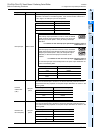
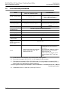
Direction sig-
nal/reverse
rotation pulse
train
(rotation
direction
signal)
Y4/6+
Y4/6-
Y004 Y006
Connect a line to determine the direction signal or the reverse
rotation pulse train for the 1st axis of each high-speed output
special adapter.
For the 1st adapter, specify Y004 as the rotation direction signal
of the positioning instruction. For the 2nd adapter, specify Y006
as the rotation direction signal output of the positioning
instruction.
Y5/7+
Y5/7-
Y005 Y007
Connect a line to determine the direction signal or the reverse
rotation pulse train for the 2nd axis of each high-speed output
special adapter.
For the 1st adapter, specify Y005 as the rotation direction signal
output of the positioning instruction. For the 2nd adapter, specify
Y007 as the rotation direction signal output of the positioning
instruction.
CLEAR signal
All output points
*1
Connect a line if it is necessary to use the DSZR/ZRN instruction
to output the CLEAR signal.
Using the CLEAR signal device specification function, specify the
output number for the transistor output. In this case, do not
specify an output device if the device is already specified for
outputting the rotational direction signal.
→ For details on the CLEAR signal device specification
method, refer to Subsection 4.3.4.
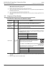
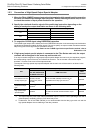
The CLEAR signal device specification register depends on the
pulse output destination as shown in the following table:
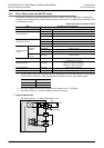
Point:
The CLEAR signal output that is initially set for the DSZR/ZRN
instruction is the same output as the direction signal (rotation
direction signal, reverse pulse train). Be sure to specify an
output number of another transistor output using the CLEAR
signal device specification function.
Pulse output destination
CLEAR signal device
specification register
Y000 D8464
Y001 D8465
Y002 D8466
Y003 D8467