


FX
3G
/FX
3U
/FX
3UC
PLC User's Manual - Positioning Control Edition
Built-in Positioning Functions
13 Troubleshooting
13.3 If the Servo Motor or the Stepping Motor Does Not Operate
B - 177
A
Common Items
B
Built-in
Positioning
Functions
Apx.
Example
Connection
13.3 If the Servo Motor or the Stepping Motor Does Not Operate
If the servo motor or the stepping motor does not operate, check the following items.
1) Check the wiring condition.
→ For output specifications, refer to Section 2.5.
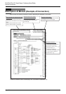
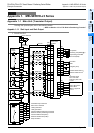
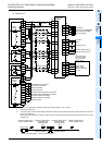
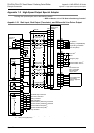
→ To connect the MELSERVO Series, refer to the examples of connection shown in the Appendix.
→ For details on the servo amplifier (drive unit), refer to the manual of your unit.
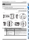
2) Execute the positioning instruction, and then check the statuses of the following LED indicator lamps.
→ For details on lamp statuses, refer to Subsection 13.1.5.
- LED indicator lamp of the output specified as the pulse output destination
- LED indicator lamp of the output specified as the rotation direction output device
3) Verify that the same pulse output method is being applied for both the PLC and the servo amplifier (drive
unit).
→ For details on the pulse output method, refer to Subsection 4.6.1.
→ For details on high-speed output special adapter setting method,refer to Subsection 4.5.2.
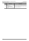
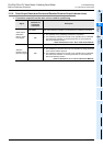
4) Check that the pulse output stop command flag is off.
→ For details on the pulse output stop command flag, refer to Subsection 4.3.2.
The following table shows the pulse output stop command flag of each pulse output destination device
(Y000, Y001, Y002, Y003).
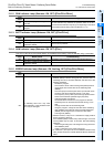
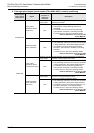
5) Check that the limit switch (forward or reverse rotation limit switch) is not activated.
→ For details on the normal and reverse rotation limits, refer to Subsection 4.3.1.
The following table shows the forward and reverse limit relays of each pulse output destination device
(Y000, Y001, Y002, Y003).
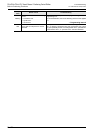
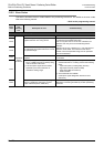
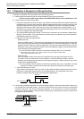
6) Check the operation timing of the positioning instruction.
If the "pulse output monitor" (BUSY/READY) flag is on, and if a positioning instruction (excluding the ABS
instruction) or pulse output instruction (PLSR, PLSY) uses the same pulse output destination device, the
instruction cannot be executed.
If the "pulse output monitor" (BUSY/READY) flag is still on after the instruction activation contact is turned
off, do not execute a positioning instruction (including PLSR and PLSY instructions) that uses the same
output number.
Before activating such an instruction, check that the "pulse output monitor" (BUSY/READY) flag is off,
and then wait until at least 1 scan time is completed.
Pulse output destination
device
Pulse output stop
command flag
Operation
Y000 M8349
During pulse outputting operation, if the pulse output stop
command flag of a corresponding pulse output destination
device is turned on, the pulse outputting operation will be
immediately stopped.
Y001 M8359
Y002 M8369
Y003 M8379
Pulse output
destination
device
Forward limit
relay
Reverse limit
relay
Corresponding instruction and stop
PLSV instruction
(M8338 = OFF)
DSZR, DVIT, ZRN,
PLSV(M8338 = ON), DRVI,
and DRVA instructions
Y000 M8343 M8344
If the corresponding rotation
limit relay is turned on, the
pulse output (operation) will
immediately stop.
If the corresponding rotation
limit relay is turned on, the
speed will decelerate, and the
operation will stop.
Y001 M8353 M8354
Y002 M8363 M8364
Y003 M8373 M8374
Pulse output destination device Pulse output monitor flag
Y000 M8340
Y001 M8350
Y002 M8360
Y003 M8370