


FX
3G
/FX
3U
/FX
3UC
PLC User's Manual - Positioning Control Edition
Built-in Positioning Functions
4 Before Programming
4.3 Various Special Relays for Operation Commands
B - 54
*1. A device can only be specified if an FX3U/FX3UC PLC Ver. 2.20 or later is used.
When using an FX
3UC PLC below Ver. 2.20, if "8" is set and then the specified interrupt positioning
(DVIT) instruction turns ON, an operation error (error code: K6763) will occur, and the instruction will
not cause any operation.
*2. Devices related to Y003 (pulse output destination) are only valid if two FX
3U-2HSY-ADP adapters are
connected to the FX
3U PLC.
*3. After setting a number in the range of 9 to E for the interrupt input signal, if the corresponding interrupt
positioning (DVIT) instruction turns ON, an operation error (error code: K6763) will occur, and the
instruction will not cause any operation.
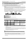
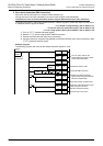
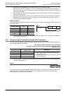
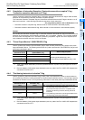
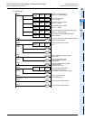
Example program:
The following program specifies the interrupt input signal for each pulse output destination device as shown in
the following table.
*1. Devices related to Y003 (pulse output destination) are only valid if two FX
3U-2HSY-ADP adapters are
connected to the FX
3U PLC.
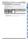
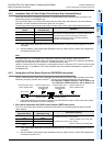
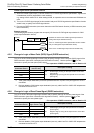
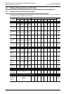
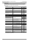
4.3.8 Change in Logic of interrupt input Signal (DVIT Instruction)
Turn the "Interrupt signal logic reverse" relay ON or OFF to specify the logic of the interrupt input signal of the
interrupt positioning (DVIT) instruction.
→ For operation of DVIT instruction, refer to Chapter 9.
→ For details on the interrupt input signal designation method, refer to
Subsection 4.3.7.
*1. Devices related to Y003 (pulse output destination) are only valid if two FX
3U-2HSY-ADP adapters are
connected to the FX3U PLC.
Caution:
If a user interrupt input command (M8460 to M8463) is specified in the interrupt input signal, the logic of the
user interrupt input command cannot be specified. This is because turning on the user interrupt input
command will turn on the interrupt input signal.
Pulse output
destination device
Interrupt input
signal
Setting value
Y000 X003 3
Y001 M8461 8
Y002 Unused F
Y003
*1
Unused F
Pulse output
destination device
"Interrupt signal logic
reverse" relay
Description
Y000 M8347
OFF: Positive logic (Turning the input ON will turn on the
interrupt input signal.)
ON: Negative logic (Turning the input OFF will turn on the
interrupt input signal.)
Y001 M8357
Y002 M8367
Y003
*1
M8377
RUN monitor
FNC 12
MOVP
HFF83 D8336
M8000
M8336