Installation, cont’d
ISS 506 Integration Seamless Switcher • Installation
2-4
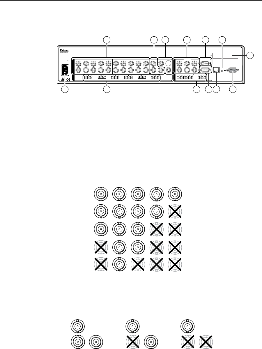
Cabling and Rear Panel Views
All connectors are on the rear panel (figure 2-2).
100-240V
50/60 Hz
2A MAX
R/
R-Y
SDI
G/Y
VID
S
B/C
B-Y
H
H/HV
V
H/HV
RS232/422
1
L
R
R/
R-Y
1
2
G/Y
VID
B/C
B-Y
R/
R-Y
G/Y
VID
B/C
B-Y
H/HV
V
H/HV
V
V
R/
R-Y
3
4
G/Y
VID
B/C
B-Y
VID
/Y
R-Y
VID
B-Y
/C
V
G
/Y
5
R
R-Y
RESET
O
U
T
P
U
T
S
6
YC
B/
B-Y
PROGRAM
PREVIEW
RGB/R-Y, Y, B-Y
RGB/R-Y, Y, B-Y
2
L
R
3
L
R
4
L
R
5
L
R
6
L
R
I
N
P
U
T
S
L
R
PREVIEW
FIXED
L
R
PROGRAM
VARIABLE
L
R
LAN
1 11
13
12
2
9
5
3 4 6
10 7
8
SDI
VID
/Y
5
6
RGB/R-Y, Y, B-Y
PREVIEW
PROGRAM
Figure 2-2 — ISS 506 rear panel connectors
Input connections
a
AC power connector — Plug a standard IEC power cord into this connector
to connect the seamless switcher to a 100 to 240 VAC, 50 Hz or 60 Hz power
source.
Video input connections
b
Input 1 through Input 4 video connectors — Connect computer or RGB
video, component video, S-video, or composite video sources to these female
BNC connectors. Figure 2-3 shows how to connect the various video formats.
RGBHV
Video
RGsB or
Component
Video
S-Video
Composite
Video
RGBS or
RGBcvS
Video
H/HV
V
G/Y
VID
H/HV
V
R/
R-Y
R/
R-Y
B/C
B-Y
G/Y
VID
B/C
B-Y
H/HV
V
R/
R-Y
G/Y
VID
B/C
B-Y
H/HV
V
R/
R-Y
G/Y
VID
B/C
B-Y
H/HV
V
R/
R-Y
G/Y
VID
B/C
B-Y
Figure 2-3 — Connections for various input video formats
c
Input 5 video connectors — Connect a component video, S-video, or
composite video source to these female BNC connectors. Figure 2-4 shows
how to connect the various video formats.
Component Video
VID
/Y
R-Y
B-Y
/C
5
S-Video
VID
/Y
R-Y
B-Y
/C
5
Composite Video
VID
/Y
B-Y
/C
5
R-Y
Figure 2-4 — Connections for input 5 video formats


