2-7
ISS 506 Integration Seamless Switcher • Installation
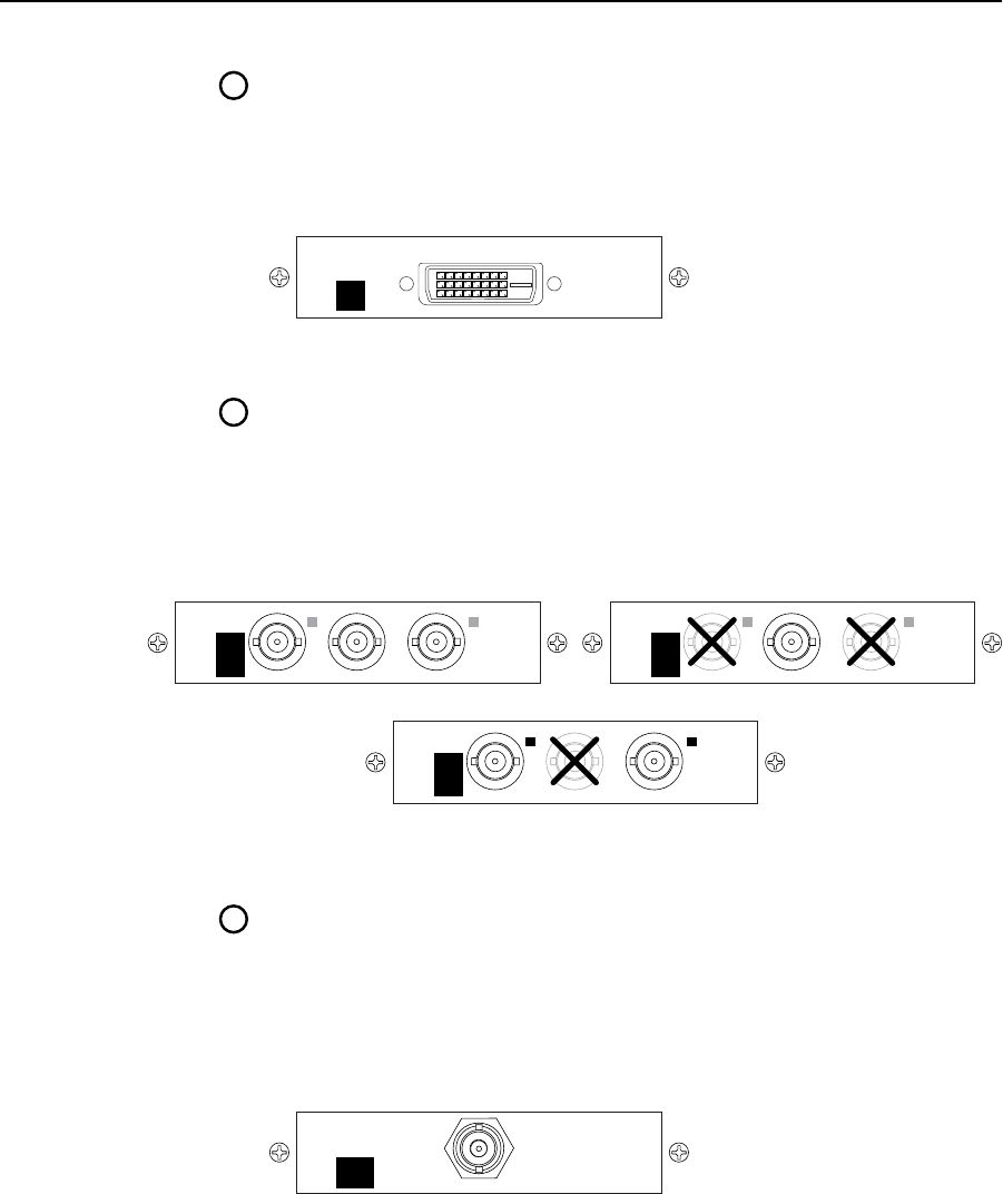
DVI output connector (optional) — If the optional DVI output board
(figure 2-9) is installed, connect a DVI/HDMI-compatible video display to
this DVI connector. This connector outputs the program image only. For
an HDMI-compatible display, connect the display through a DVI-to-HDMI
adapter, part #26-497-01 (DVI [male] to HDMI [female] adapter) or 26-498-01
(DVI [female] to HDMI [male] adapter).
Figure 2-9 — Optional DVI output board
Scan converter output connectors (optional) — If the optional scan converter
output board is installed, connect a low resolution video (RGsB video,
interlaced component video, S-video, or composite video) display to these
female BNC connectors. These connectors output the program image only.
Figure 2-10 shows how to connect the various video formats.
N
The scan converter board can output S-video and composite video
simultaneously.
LO-
RES
OUT
R-Y/
R
C
Y/
G
VID
B-Y/
B
Y
Component or RGsB Video
LO-
RES
OUT
R-Y/
R
C
Y/
G
VID
B-Y/
B
Y
Composite Video
LO-
RES
OUT
R-Y/
R
C
Y/
G
VID
B-Y/
B
Y
S-Video
Figure 2-10 — Optional scan converter output board
HD-SDI output connectors (optional) — If the optional HD-SDI output
board is installed, connect an HD-SDI display to this female BNC connector
(figure 2-11). This connector outputs the program image only.
N
You must set the scaler’s output rate to 720p (at 25, 30, 50, 59.94, or 60 Hz),
1080i (at 50, 59.94 or 60 Hz), or 1080p (at 24, 25, or 30 Hz) for the HD-SDI
board to produce an output. See “Resolution and refresh rate submenu“ in
chapter 3, “Operation”.
Figure 2-11 — Optional HD-SDI output board


