Installation, cont’d
ISS 506 Integration Seamless Switcher • Installation
2-8
Audio output connections
j
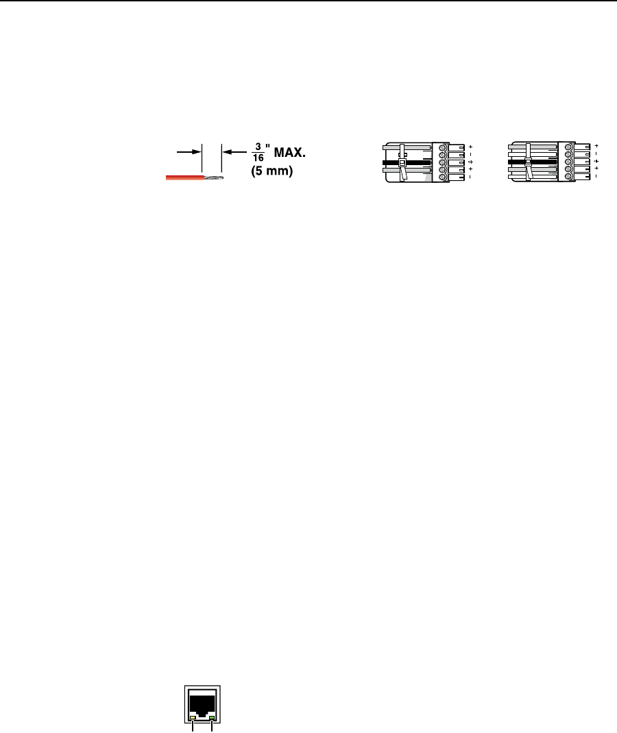
Preview and Program audio output connectors — Connect audio devices,
such as an audio amplifier or powered speakers, to these 3.5 mm, 5-pole
captive screw connectors. The connectors output the selected unamplified,
line level audio. See figure 2-12 to properly wire an output connector.
Use the
supplied tie-wrap to strap the audio cable to the extended tail of the connector.
Unbalanced Stereo Output Balanced Stereo Output
L R
Do not tin the wires!
Ring
Sleeve(s)
Tip
Tip
Ring
Sleeve(s)
Tip
Tip
NO GROUND HERE.
NO GROUND HERE.
Figure 2-12 — Captive screw connector wiring for audio output
C
Connect the sleeve to ground (Gnd). Connecting the sleeve to a
negative (-) terminal will damage the audio output circuits.
C
The length of the exposed (stripped) portion of the copper wires is
important. The ideal length is 3/16" (5 mm). Longer bare wires can
short together. Shorter bare wires are not secure enough in the direct
insertion connectors and could be pulled out.
N
The level of the audio output on the Variable Program output connector can be
adjusted using the front panel Volume control.
The Preview Output and the Fixed Program output connectors are not affected
by the front panel Volume control.
By default, the audio output follows the video switch. Audio breakaway,
commanded via the Ethernet link or the RS-232/RS-422 link, allows you
to select from any one of the audio input sources. See chapter 4, “SIS
Programming and Control”; chapter 5, “Scaler Software”; and chapter 6,
“Ethernet Operation”, for details.
Control connections
Ethernet connection
k
LAN port — If desired, connect the seamless switcher to an Ethernet LAN or
WAN via this RJ-45 connector. Ethernet control allows the operator to control
the seamless switcher from a remote location. When connected to an Ethernet
LAN or WAN, the seamless switcher can be accessed and operated from a
computer running a standard Internet browser.
Ethernet connection indicators — The Link and Activity LEDs indicate the
status of the Ethernet connection.
The Link LED indicates that the seamless switcher is properly
connected to an Ethernet LAN. This LED should light steadily.
The Activity LED indicates transmission of data packets on the
RJ-45 connector. This LED should flicker as the seamless switcher
communicates.
Cabling and RJ-45 connector wiring
It is vital that your Ethernet cables be the correct cables, and properly terminated
with the correct pinout.


