2-5
ISS 506 Integration Seamless Switcher • Installation
d
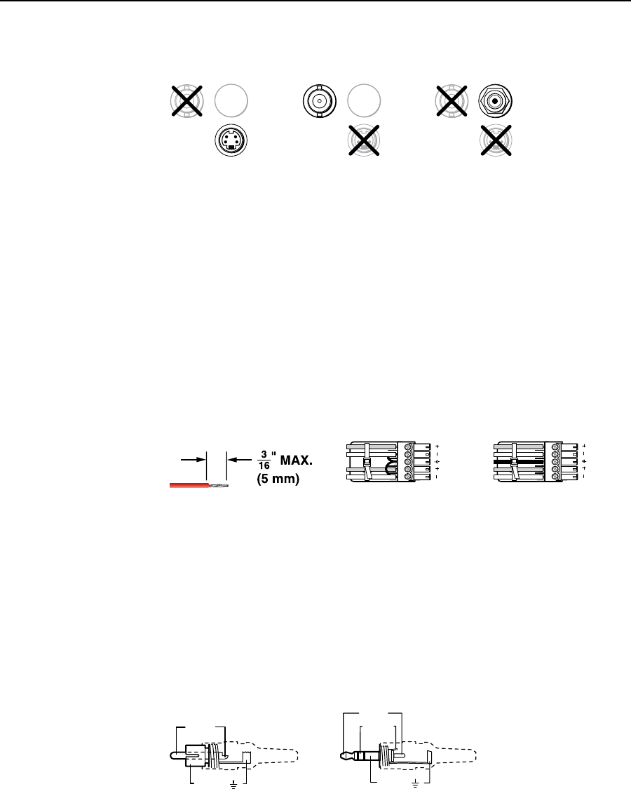
Input 6 video connectors — Connect either an S-video, a composite video, or
an SDI/HD-SDI video source to these connectors (figure 2-5).
VID
6
YC
SDI
VID
6
YC
VID
6
YC
SDI
Composite Video SDI or HD-SDI Video
(Optional SDI/HDSDI Input Board Only)
S-Video
SDI
Figure 2-5 — Connections for input 6 video formats
N
The SDI/HD-SDI video input is available only on the ISS 506 DI/DVI, the
ISS 506 DI/SC, and the ISS 506 DI/HD-SDI.
N
Although all video formats can be physically connected, input 6 cannot accept
multiple video inputs simultaneously.
Audio input connections
e
Input audio connectors — Connect balanced or unbalanced stereo or mono
audio to these 3.5 mm, 5-pole captive screw connectors. Connectors are
included with the seamless switcher, but you must supply the audio cable.
Figure 2-6 shows how to wire a connector for the appropriate input type.
Use
the supplied tie-wrap to strap the audio cable to the extended tail of the connector.
High impedance is generally over 800 ohms.
L R
L R
Unbalanced Stereo Input
Balanced Stereo Input
(high impedance)
(high impedance)
Do not tin the wires!
Ring
Sleeve (s)
Tip
Sleeve
Tip
Sleeve
Tip
Tip
Ring
Figure 2-6 — Captive screw connector wiring for inputs
C
The length of the exposed (stripped) portion of the copper wires is
important. The ideal length is 3/16" (5 mm). Longer bare wires can
short together. Shorter bare wires are not secure enough in the direct
insertion connectors and could be pulled out.
N
When making connections for the seamless switcher from existing audio cables,
see figure 2-7. A mono audio connector consists of the tip and sleeve. A stereo
audio connector consists of the tip, ring, and sleeve. The tip, ring, and sleeve
wires are also shown on the captive screw audio connector diagram, figure 2-6.
Tip (+)
Sleeve ( )
Sleeve ( )
Ring (
-
)
Tip (+)
RCA Connector
3.5 mm Stereo Plug Connector
(balanced)
Figure 2-7 — Typical audio connectors
The audio level for each input can be individually set via the front panel, the
Ethernet link, or the RS-232/RS-422 link, to ensure that the level on the output
does not vary from input to input. See chapter 3, “Operation”, chapter 4,
“SIS
Programming and Control”; and chapter 5, “Scaler Software”, for details.


