2-11
ISS 506 Integration Seamless Switcher • Installation
Front Panel Configuration Port
TRANSITION
PICTURE
ADJUSTMENTS
CONFIG
ZOOM
TAKE
PIP
TITLE
SIZE DETAIL
POSITION
BRIGHT/
CONT
COLOR/
TINT
ISS 506
Integration Seamless Switcher
VOLUME
ADJUST
ADJUST
MENU
NEXT
14
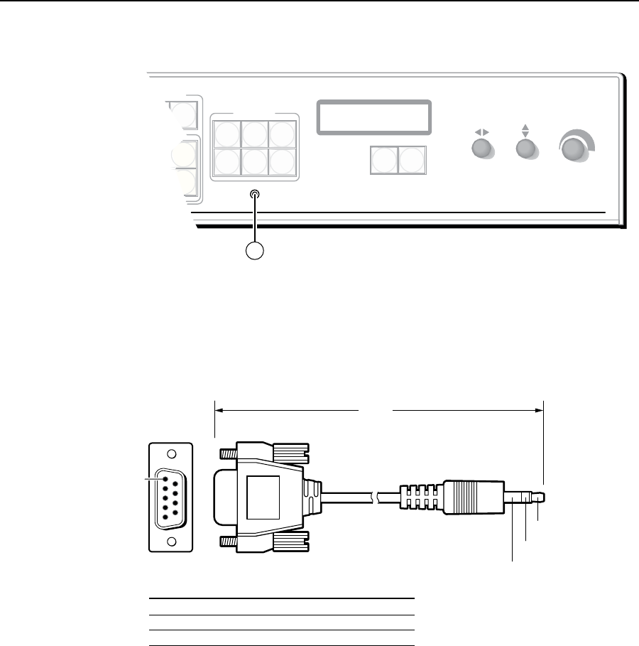
Figure 2-15 — Front panel configuration port
n
Configuration port — This 2.5 mm mini stereo jack serves the same serial
communications function as the rear panel Remote port, but it is easier
to access than the rear port after the matrix switcher has been installed
and cabled. The optional 9-pin D to 2.5 mm mini jack TRS RS-232 cable,
part #70-335-01 (figure 2-16), can be used for this connection.
6 feet
(1.8 m)
Part #70-335-01
5
1
9
6
Sleeve (Gnd)
Ring
Tip
9-pin D Connection TRS Plug
Pin 2 Computer's RX line Tip
Pin 3 Computer's TX line Ring
Pin 5 Computer's signal ground Sleeve
Figure 2-16 — Optional 9-pin TRS RS-232 cable
N
This port is independent of the rear panel RS-232/RS-422 port. A front panel
Configuration port connection and a rear panel RS-232/RS-422 port connection
can both be active at the same time.
This port is RS-232 only, with its default protocols as follows:
• 9600baud • noparity • 8databits
• 1stopbit • noowcontrol
N
The maximum distance from the seamless switcher to the controlling device
can vary up to 200 feet (61 m). Factors such as cable gauge, baud rates,
environment, and output levels (from the switcher and the controlling device)
all affect transmission distance. Distances of about 50 feet (15 m) are typically
not a problem. In some cases the matrix switcher may be capable of serial
communications via RS-232 up to 250 feet (76 m) away.


