Intel
®
IXP400 Software
Endianness in Intel
®
IXP400 Software
April 2005 IXP400 Software Version 2.0 Programmer’s Guide
350 Document Number: 252539, Revision: 007
27.4.3.2 Intel XScale
®
Core Endianness Mode
The Big- and Little-Endian modes are controlled by the B-bit, located in the “Intel StrongARM
Control Register”, coprocessor 15, register 1, bit 7. The default mode at reset is Little-endian. To
enable the Big-Endian mode, the B bit must be set before performing any sub-word accesses to
memory, or undefined results would occur. The bit takes effect even if the MMU is disabled. The
following is assembly code to enable/clear the B-bit.
MACRO LITTLEENDIAN
MRC p15,0,a1,c1,c0,0
BIC a1,a1,#0x80 ;clear bit7 of register1 cp15
MCR p15,0,a1,c1,c0,0
ENDM
MACRO BIGENDIAN
MRC p15,0,a1,c1,c0,0
ORR a1,a1,#0x80 ;set bit7 of register1 cp15
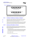
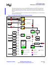
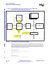
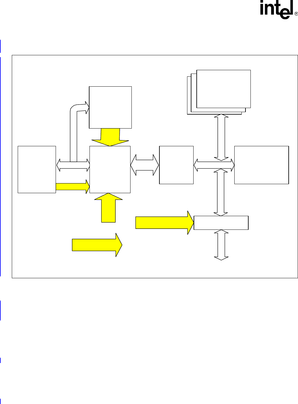
Figure 116. Intel
®
IXP4XX Product Line of Network Processors and IXC1100
Control Plane Processor Endianness Controls
B3810-001
Memory Subsystem
(SDRAM)
NPE’s
Addr/Data Bus Bus
Bus
Intel XScale
®
Core
Intel XScale
®
Core
Endianness
Conversion logic
Addr/data
bus
Cache
MMU
Tables
L
E
c
o
n
t
r
o
l
(
P
-
B
i
t
)
XScale LE
Expansion
Ctrl CFG 2
NPE’s
NPEs
Bus
PCI Controller
PCI Bus
PCI Endianess sw ap
control
Under software
control
B3810-001
Memory Subsystem
(SDRAM)
NPE’s
Addr/Data Bus Bus
Bus
Intel XScale
®
Core
Intel XScale
®
Core
Endianness
Conversion logic
Addr/data
bus
Cache
MMU
Tables
L
E
c
o
n
t
r
o
l
(
P
-
B
i
t
)
XScale LE
Expansion
Ctrl CFG 2
NPE’s
NPEs
Bus
PCI Controller
PCI Bus
PCI Endianness sw ap
control
Under software
control


