


Intel
®
IXP400 Software
Endianness in Intel
®
IXP400 Software
Programmer’s Guide IXP400 Software Version 2.0 April 2005
Document Number: 252539, Revision: 007 357
27.5.3.4.1 Data Plane
The data plane interface for IxEthAcc uses the IxQMgr component to send/receive messages
between the Ethernet access and the Ethernet NPEs. All messages transferred are word-wide (32-
bit) messages. These messages are modified by the underlying access layer because the AHB
Queue Manager hardware FIFOs are mapped using Data Coherent Little-Endian (as described in
“Queue Manager — IxQMgr” on page 355).
Note: The AHB Queue Manager can be I/O mapped into memory using either data or address Coherent
conversions, and the IxQMgr software will operate correctly in either mode, transparent to the
client.
The messages sent/received from the NPE contain a pointer reference to an IX_OSAL_MBUF, and
more specifically to the NPE specific structure within the IX_OSAL_MBUF. See the Chapter 3 for
more information.
The SDRAM is mapped using Data Coherency mode for all areas. This introduces two specific
areas of consideration:
• NPE interpretation of the IX_OSAL_MBUF
• NPE interpretation of the data payload.
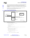
27.5.3.4.2 IX_OSAL_MBUF Data Payload
The Ethernet access-layer component does not impose any alignment restrictions on the ix_data
pointer within the IX_OSAL_MBUF. The primary consideration in selecting the Little-Endian
coherence mode (as Data Coherent) is the expectation the standard BSD IP stack places on the data
format for payloads.
The BSD IP stack makes extensive use of the htons, htonl primitives to extract IP/UDP/TCP header
information within the stack. These are described in “Macro Examples: Endian Conversion” on
page 345.
BSD IP Stack summary:
• Bytes can be read with a byte pointer.
• All half-word reads must be half-word-aligned and use htons/ntohs for conversions.
• All word reads must be word-aligned and use htonl/ntohl for conversions.
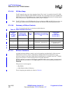
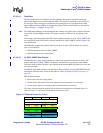
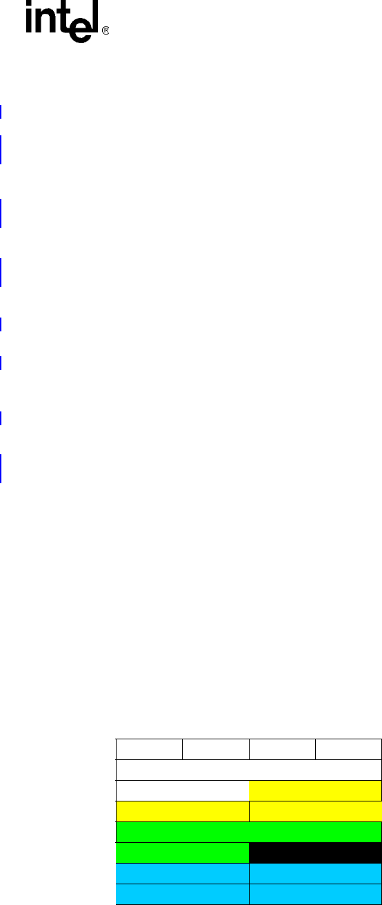
The issues associated with the payload will be discussed in reference to an Ethernet frame. As
shown in Figure 117, the frame is described in network byte order.
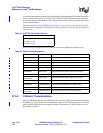
Figure 117. Ethernet Frame (Big-Endian)
D0 D1 D2 D3
DA[0] DA[1]
DA[2] DA[3] DA[4] DA[5]
SA[0] SA[1] SA[2] SA[3]
SA[4] SA[5] Type/Len
ver/hlen TOS 16-bit-Len
Identification flag/Fragment offset