


Intel
®
IXP400 Software
Buffer Management
April 2005 IXP400 Software Version 2.0 Programmer’s Guide
38 Document Number: 252539, Revision: 007
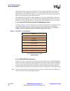
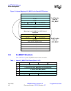
3.3 IXP_BUF Structure
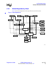
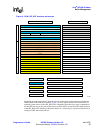
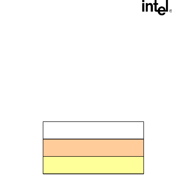
As shown in Figure 5, IXP_BUF is comprised of the following three main structures, and each
structure is comprised of eight entries four bytes long.
1. The first structure consists of an eight word fields some of which are between the OS driver /
API users and the access-layer components.
2. The second structure consists of internal fields used by the pool manager, which is provided by
the OSAL component.
3. The third structure is the NPE Shared structure that is composed of common header fields and
NPE service specific fields. Depending upon the access-component usage, some of the service
specific fields such as VLAN tags may be available for the user through use of macros.
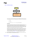
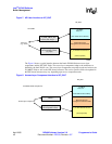
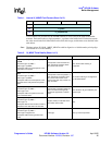
3.3.1 IXP_BUF Structure and Macros
Users are expected to use the following IXP_BUF macros provided to access IXP_BUF subfields.
The Figure 6 shows macros defined by the OSAL layer component to be used to access the
IXP_BUF fields.
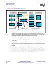
Figure 5. IXP_BUF Structure
B-3826
IX_MBUF: OS Dependent Buffer format
Structure 1
Structure 3
Structure 2
ix_ctrl: Pool Management Fields
ix_ne: NPE Shared structure
IXP_BUF structure