267Setup Relating to DCU
Chapter 16 Engineering Setup
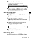
• Press the arrow keys to scroll the reverse video cursor.
• Turn the knob to make the setting.
2
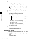
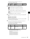
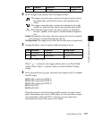
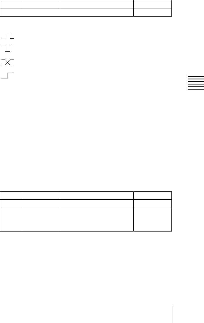
In the <Trigger Type> group, select the trigger polarity.
: Apply the trigger on a rising edge of an input pulse.
: Apply the trigger on a falling edge of an input pulse.
: Apply the trigger on a change in the polarity of the input signal.
(Level): Carry out the specified operation when the input is low or
high.
No Operation: Apply no trigger on an input pulse.
3
In the <Target Device> group, select the control panel to handle the GPI
input.
SCU1: ID1 control panel (PNL1)
SCU2: ID2 control panel (PNL2)
SCU3: ID3 control panel (PNL3)
The action set in the following step 4 is executed for the switcher and DME
controlled by the selected control panel.
4
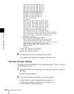
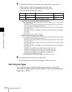
Using any of the following methods, select the action you want to set.
• Press directly on the list appearing in the status area.
• Press the arrow keys to scroll the reverse video cursor.
• Turn the knobs to make the setting.
a) • Action list when the trigger type is other than “Level”
M/E-1 Cut, M/E-2 Cut, M/E-3 Cut, P/P Cut,
M/E-1 Auto Trans, M/E-2 Auto Trans, M/E-3 Auto Trans,
P/P Auto Trans
M/E-1 Key1 Auto Trans, M/E-1 Key1 Cut
M/E-1 Key2 Auto Trans, M/E-1 Key2 Cut
M/E-1 Key3 Auto Trans, M/E-1 Key3 Cut
M/E-1 Key4 Auto Trans, M/E-1 Key4 Cut
M/E-2 Key1 Auto Trans, M/E-2 Key1 Cut
M/E-2 Key2 Auto Trans, M/E-2 Key2 Cut
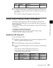
Knob Parameter Adjustment Setting values
1 No GPI input 1 to 50
Knob Parameter Adjustment Setting values
2 Action Action selection
1 to ...
a)
5 Reg No Register number
1 to 4
b)
1 to 99
c)
1 to 399
d)


