


o
o
o
o
o
o
o
o
o
o
o
o
o
o
o
o
o
o
o
o
o
o
o
o
o
o
o
o
o
o
o
o
o
o
O
o
o
o
o
o
o
o
o
o
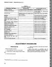
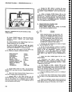
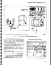
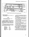
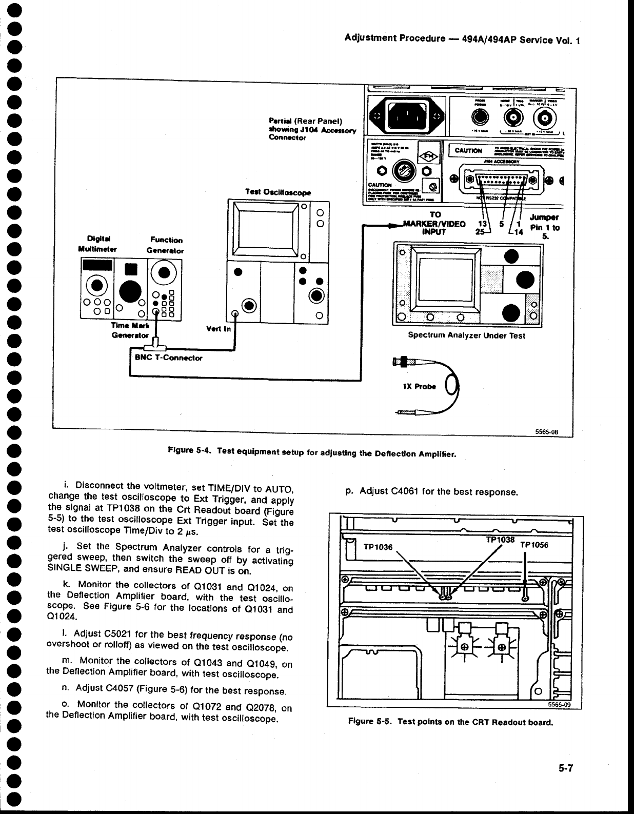
Figure
5-4. Test
equlpment
setup for
adiusting
the
D€flection
Amplifier.
Adiustment
Procedure
-
4g4Al4g4Ap
Service
Vol.
1
p.
Adjust
C4061 for
the best
response.
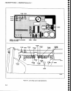
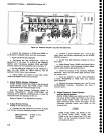
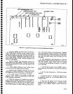
Figure
5-5.
Test
points
on
the
CRT
Readout
board.
i.
Disconnect
the
voltmeter,
set
TIME/DIV
to
AUTO,
change
the
test oscilloscope
^to
Ext
Trigger,
and
apply
the signat
at
Tp10g8
on
the
Crt
neadojt-board
fiiuri
5-5)
to
the
test oscilloscope
Ext
Trigger
input.
Set
the
test oscilloscope
TimeiDiv
to
2
;rs.
j.
set
the
spectrum
-
Analyzer
controls
for
a
trig-
gered
sweep,
then
switch
the sweep
off
by
aetivating
SINGLE
SWEEP,
and
ensure
netO
OUT is
on.
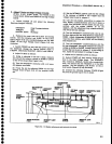
k.
Monitor
th€ collectors
of
e1O31
and
e1
024,
on
the Deflection
Amplifier
board,
with
the
test
oscillo-
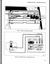
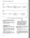
See Figure
5-6 for
the locations
of
e1031
and
01024.
l.
Adjust
C5021 tor
the
bestfrequencyresponse(no
overshoot
or
rolloff)
as
viewed
on
the
tesiosciiloscope,
m.
Monitor
the collectors
of
e1043
and
e1049,
on
the Deflection
Amplifier
board,
with
test oscilloscope.
n.
Adjust
C4OS7
(Figure
5_6) for
the
best
response.
o.
Monitor
the collectors
of
e1072
and
e207g,
on
the
Deftection
Amplifier
board,
with
test o."illo."op".
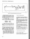
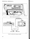
P.rtad (Rear
Panel)
drowing
Jl(X
Acccrorv
Connrcror
a
@
@
JgESI
(
5 1
1{
Jumpcr
Pin I
to
5.
BllC
T-Conneclor
T.d
O|Glnoacopc
o
ooo
Oo
Spectrum Analyzer
Under Test
5-7