o
o
o
o
o
o
I
o
o
O
o
a
O
a
t
o
a
o
o
a
O
o
a
o
a
o
t
o
a
O
I
o
I
o
o
o
o
o
o
o
o
a
o
o
g.
.With
the
adjacent
resonator
(second)
shorted
to
ground,
adjust
the
series
capacitance
by
benOing
tne
tab
so
the response
on
the_spectrum
analyzer
display
is
centered
at
829
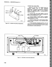
MHz (see
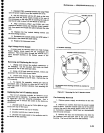
Figure
6_16A).
-
h.
Now
move
the
shorting
strap
(screwdriver)
to the
next
resonator
and
adjust
the
tab of
the second
resona_
tor
for
a response
as
indicated
in
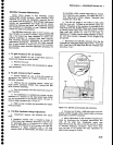
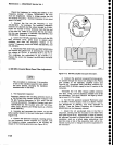
Figure
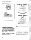
OiOe.
i.
Remove
the
short
from
the
third
resonator
and
short
the fourth
resonator.
Adjust
the
third
resonator
for
a
response
similar
to
that
snown
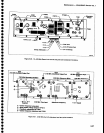
in Figure
6-1
7A.
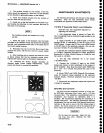
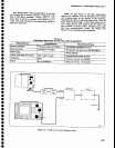
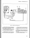
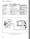
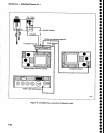
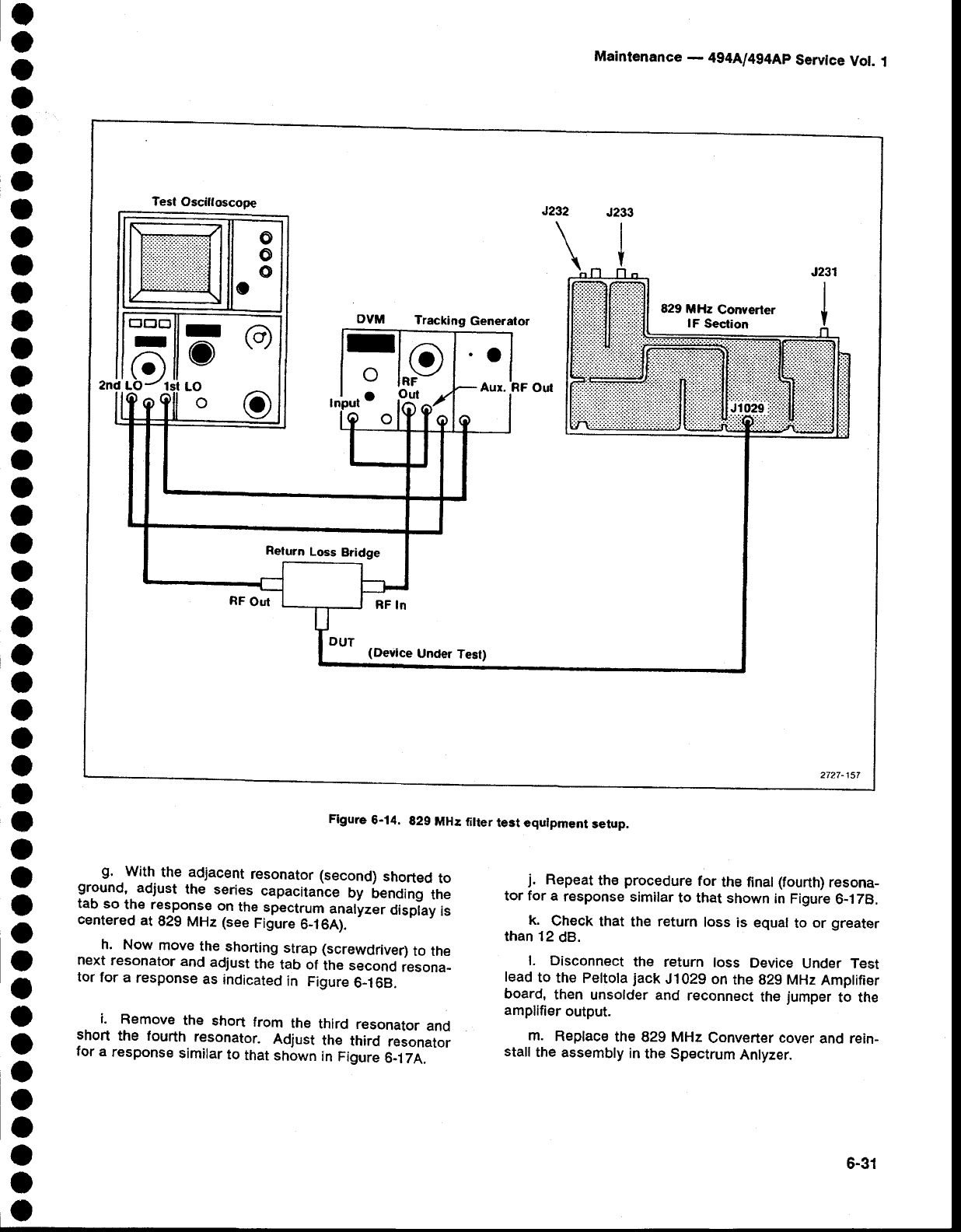
Flgure
6-14.
829
MH:
filter
test equlpment
setup.
Maintenance
-
494[l4g4Ap
Servlce
Vot.
I
j.
Repeat
the
procedure
for
the final
(fourth)
resona-
tor
for
a
response
similar
to
that shown
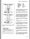
in Figure
6-178.
k.
Check
that
the
return
loss
is equal
to
or
greater
than
12
dB.
l. Disconnect
the
return
loss
Device
Under Test
lead
to
the
pettota
jack
J1029
on
the
g29
MHz
Amptifier
board,
then
unsolder and
r€connect
the
jumper
to the
amplifier
output.
m.
Replace
the
829 MHz
Converter cover
and rein-
stall
the
assembly
in
the
Spectrum
Anlyzer.
o
o
o
o
Test
Osciltoscope
Tracking
Generator
829
MHz
Converter
lF
Section
J231
I
I
Y
I
o
__^
a
lo
IRF
Out
.O
Aur.
(Device
Under
Test)
2727-157
Return
Loss
Bridge
6-31


