


Mafntenance
-
494A1494Ap
Service
Vot.
1
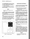
Some circuit
boards and
assemblies
must
be
placed
on
extenders
to access
test
points
or
adjustments.
Before
removing
these
boards
and
assembli6s,
the
air
bafie
attached
to
the
left
siderail
must
also
be
r€moved.
Turn
the
power
off
before
removing
an
assembly.
Removing
and
Installing
the
GplB Board
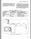
The
GPIB
board connects
to the
GplB port
on
the
back
panel,
through
a
GptB
Extend€r
board (A56A1),
a
ribbon
cable
(W560),
and
a
GplB Interface
board
(A30A54
in
the Power
Suppty modute.
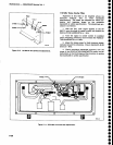
The
GptB
Extender
board
edge
connector
is
clamp€d
to
th€ con_
nector
on
the
GPIB
board
by means
of
a locking
key
that
extends
through
the
connector.
When
the
fly
ii
turned,
so
it faces inward,
the
connector
is clamped.
To
release
the
connector,
so
the GplB
board
can
be
removed,
proceed
as follows:
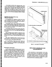
1.
Unscrew
the
mounting
screws
that
hold
the
metal
shield
over
the
GPIB,
processor.
and
Digital
Storage
boards
and
remove
the shield.
2. Lift
th€
key
to the
GptB
Extender
board
connec-
tor up so
it
iust
clears
the
board
and
turn
it
gO
degrees,
so
it
faces
the
rear
of
the instrument.
This
will
spread
the
connector
so
the GPIB
board can
now
be
pull
from
the connector
on
the
Mother
board.
3.
Use a
board
puller
to
pull
the
GplB
board free
from
the Mother
board.
lnstall the
board as tollows:
1. With
the
key
tor
the
GplB
Extender
board
con-
nector
turned so the connector
is spread
(top
of
the key
facing
to the
rear of
the
instrument),
slide
the GplB
board
through
the
guides
and onto
the
Mother
board
connector.
Ensure
that the
board
is well
seated.
2. Turn
the
key
90
degrees
to lock
the
connectors
of
the GPIB Extender
board and
the
GplB
board
together. Push
the key
down
to
its rest
position.
3.
Re-install
the shield
over
the GplB,
processor,
and
Digital
Storage
boards.
Removing
or Replacing
Semi-rigid
Coaxial
Cables
Performance
of
the
instrument
is
easily
degraded if
these connectors
are
loose,
dirty,
or
damaged.
The fol-
lowing
procedure
will
help ensure
that
the
connection
is
good
enough
to maintain
proper
performance.
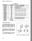
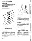
1.
Use a
5/1 6
inch
open-end
wrench
to
loosen
or
tighten
the
connectors.
lt is
good practice
to use a
second
wrench
to hold
the rigid
(receptacle)
portion
of
the connector
to
prevent
bending
or
twisting
the cable.
6-22
2. Ensure
that
the
plug
and
receptacle
are
clean
and
free of any
foreign
matter.
3.
Insert
the
plug
connector fully
into
the
receptacte
before screwing
th€ nut
on.
Tighten
th€
connection
to
g
in-lbs
to
ensure
that
the
connection
is
tight. Do
not
overtighten ('l5
to
20
in-lbs)
because
this
can
damage
the connector.
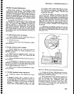
Replacing
lhe Dual Diode
Assembly
in
the 1st Mixer
The
diode subassembly
that
houses
the Schottky
mixer
diodes
permits
easy
field
replacement of
the
diodes.
The subassembly
is secured in
place
with
four
0-80
screws.
An
8-32
threaded hole is
provided
to facil-
itate insertion
and
removal of
the
subassembly.
There
are three contact
points
located on
the
substrate
side
of
the
subassembly.
Use
care
to
ensure
proper
fit when
mounting and orienting
these
contacts in
the mixer
assembly.
Insertion
and
removal
of
the
subassembly
more
than twice
is not
recommended
due to
th€
gold-
ribbon
attaching
technique
used in
fabrication.
'
A
tuning
screw
is
adjusted
to
null a
start spur
on
Band
1.
This
tuning screw is mounted
through the
top
of
the
diode asssembly,
adjacent
to
the
8-32 hole.
lf
adjustment
of
this
screw
is warranted. care should
be
taken to not force
the tuning
screw
after
it
bottoms out
on
the
surface
of
the
quartz-suspended
substrate.
The diode
assembly is
packaged
in
a static-free
package.
Keep
the
diode
subassembly in this
package
until
ready
to install. The following
should
be used
when replacing
this
assembly.
The diodes are
beam-lead
devices,
mounted
on
a
quartz-suspended
substrate.
These diodes are
extremely sensitive to
static electricity
discharge.
Refer to the
caution
note on static discharge
at the
beginning
of
this
section. Do
not expose
the diode
assembly
to
RF fields.
1. Loosen and
disconnect
the three
coaxial
cable
connections at
the
1st
converter
assembly.
2. Remove
the
two
mounting
screws,
and
remove
the
assembly
from the
instrument.
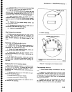
3.
Remove
the four 0-80
screws that
hold the diode
subassembly
in the
1st
Converter,
and insert
a
8-32
screws into
the threaded
hole
provided
in the
center of
the diode
assembly.
4. Lift
the
diode
assembly out
of
the
mixer
assem-
bly by
m€ans
of
the 8-32
screw, then remove
the
screw.
o
o
o
o
o
o
o
o
o
o
o
o
o
o
o
o
o
a
o
o
o
o
o
O
o
O
o
o
o
o
I
O
o
o
o
O
o
o
o
o
o
o
o
o