


o
o
o
a
O
o
o
I
O
o
I
a
o
a
o
I
o
I
O
o
o
a
o
o
o
o
a
o
t
I
o
O
O
o
o
o
o
t
a
o
o
o
o
o
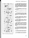
(29)
Press
RECALL
SETTTNGS
2.
!30)
Adjust
C4060.
in
the 10
Hzl100
Hz
Bandpass
Filter
assembly
for
best
symmetry.
lgtt
Repeat parts
2g
through
31
to
etiminate
interaction.
(32)
Remove
ail
jumpers
from
the
10 Hzl100
Hz
Bandpass
Filter
assembly.
(33)
press
<Btue-SHtFT>
CAL
to
start
the internat
calibration
routine.
press
FINE
to
continu€
calibra_
tion
as
prompted.
K.
RCSCT
thE RESOLUTION
BANDWIDTH
tO
1OO
HZ
and
FREQ
SpAN/Dtv
to
50
Hz.
set
the
REF
LEVEL
su-ch
that
the response
is
near
the amplitude
of
the
reference.
L
Disconnect
the
10
MHz
third
converter
lF
signal
from
J683 and
reconnect
it
to
J690.
Reconnect
p6g3
to
J683.
m.
set
the FREQ
spAN/DlV
to
1
kHz,
RESOLU-
TION
BANDWIDTH
to
1
kHz
and
reset
the
REF
LEVEL
tor
a
7 division
disptay.
Activate
SAVE
A.
n.
set
th€
FREQ
spAN/DtV
to
10
kHz,
RESOLU-
TION
BANDWTDTH
to
10
kHz
and
adjust
REF
LEVEL
for
a
7
division
display.
o.
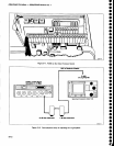
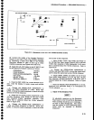
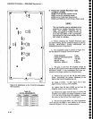
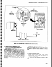
Adjust
C2030
(Figure
5-1S)
for
the
best
1O
kHz
response
centered
about
the
1
kHz
reference.
Adjustnent
Procedure
-
4g4[l4g4Ap
Service
Vot.
1
p.
Deactivate
SAVE
A and
then reactivate
to
save
the
10
kHz
display.
q.
Set
FREQ
SPAN/D|V
to 50 kHz
and
RESOLU_
TION
BANDWIDTH
to 100 kHz.
,
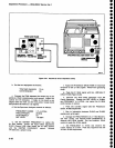
r.
Adjust
C3045,
C3039,
and
C3030
(Figure
5_15)
for
the
best
100
kHz
response
centered
about
the
10 kHz
filter
reference.
s.
Check
the waveshape,
bandwidth, and
centering
of all
filters.
lf necessary,
make only
fine or
minor
adjustments.
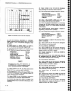
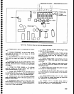
Figure
5-1
g
shows
typical
response
shapes.
t.
Level
th€
gain
of
the
filters
as follows:
(1)
SCt thE
FREQ
SPAN/DIV
tO
5OO KHZ,
RESOLU-
TION
BANDWIDTH
to
1OO
KHz,
and REF
LEVEL
to
-20
dBm.
(2)
Adjust all
filters
to
the 1OO
kHz tevet as
p€r
the
follovying
Table
5-3. Change
FREQ
SPANIDIV
as
necessary
to maintain
a
"suitable
display.
u. Press
<Blue-SHtFT>
PULSE
STRETCHER
(DIAGNOSTIC
FUNCTTONS)
and setect
item
#s
(DISABLE/ENABLE
USE
OF
CAL FACTORS),
then
item
#1 (USE
RESULTS),
to
re-enable
use
of cal
factors.
ocrttt? to.t2l,
too
ArLlEi
d
@.*.'
@t*
--;o,-.*
R'm3
GnEo'
66-//
6*@
oooo@
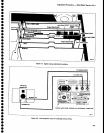
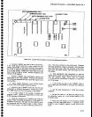
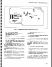
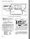
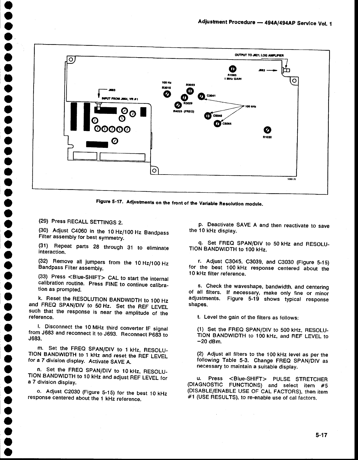
Figure
5-17.
Adiu3tments
on
the front
of the
Variabte
Resolution
module.
5-17