


Adlustment
Procedure
-
494A/494Ap
Servlce
Vot. 1
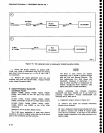
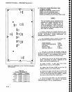
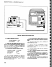
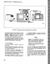
Figure
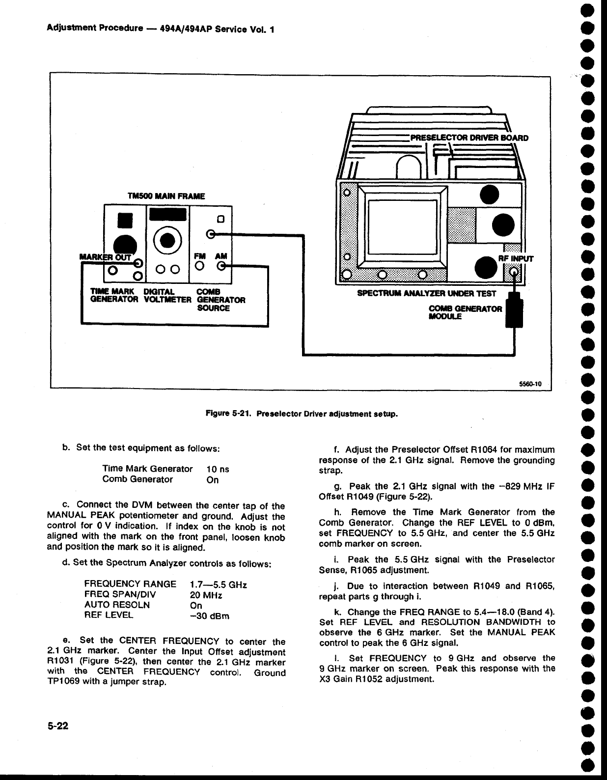
5-21. Preselector
Driver adiustment
lietup.
o
a
o
o
o
o
o
I
o
o
I
a
a
a
I
o
o
)
o
a
o
o
a
O
o
o
o
o
t
o
o
a
O
O
O
o
o
o
o
o
I
o
o
o
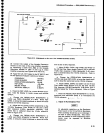
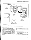
b. Set
th€
test equipment
as follows:
Time Mark
Generator
.l
0 ns
Comb
Generator
On
c.
Connect
the DVM
between
the
center
tap
of
the
MANUAL PEAK
potentiometer
and
ground.
Adjust
the
control
for
0 V
indication.
lf
index
on
the knob
is
not
aligned
with
the mark
on
the
front
panel,
loosen
knob
and
position
the
mark
so
it is aligned.
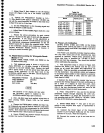
d. Set
the
Spectrum
Analyzer
controls
as
follows:
FREQUENCY
RANGE
1.7-5.5
GHz
FREQ
SPAN/D|V
20
MHz
AUTO
RESOLN
On
REF
LEVEL
_30
dBm
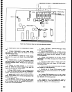
E.
SEt
thE CENTER
FREQUENCY
tO CENIET
thE
2.1 GHz markEr.
Center
the
Input
Ofiset adjustment
R1 031
(Figure
5-221,
then
center
the 2.1
GHz
marker
with the
CENTER
FREQUENCY
control.
Ground
TP1069 with
a
jumper
strap.
f. Adjust
the
Preselector Offset Rl064
for
maximum
response
of
the
2.1
GHz
signal. Remove
the
grounding
strap.
s.
Peak
the
2.1
GHz
signal with
the
-829
MHz
lF
Ofiset R1049
(Figure
5-22).
h, Remove the Time
Mark
Generator from the
comb Generator. change the REF LEVEL to 0
dBm.
set
FREQUENCY
to 5.5 GHz,
and center
the 5.5
GHz
comb
marker
on
screen.
i. Peak
the 5.5 GHz
signal
with
the
Preselector
Sense,
R1
065
adjustment.
j.
Due
to
interaction
between R1049
and
R1065,
repeat
parts g
through i.
k.
change
the FREQ RANGE
to
5.4-18.0
(Band
4).
S€t
REF
LEVEL
and
RESOLUTION BANDWIDTH
to
obsgrve
the 6
GHz marker. Set
the
MANUAL
PEAK
control to
peak
the 6 GHz signal.
l.
Set FREOUENCY
to
9 GHz
and
observe
th€
9
GHz
marker on screen.
Peak
this
response
with
the
X3 Gain
Rl052 adjustment.
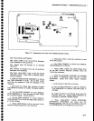
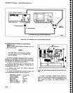
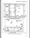
PRESEIECTON OR]YER EOARD
Ttrsoo
MAN
FRATE
OTi#i"
SPECTRT I
AilALYZER lrl'DER
TEST
OMGEilERATOR
f,OOIJLE
I
o
oo
NETARK
DIGITA
OOTB
GilERffOR
VOLTreTER
GEilERATOR
SOURCE
5-22