o
I
o
o
o
o
o
I
o
e
I
o
o
o
a
o
{l
I
I
a
I
o
o
a
o
o
e
o
o
I
o
o
o
o
i
o
I
I
o
a
C
o
o
a
l.
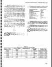
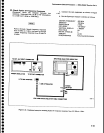
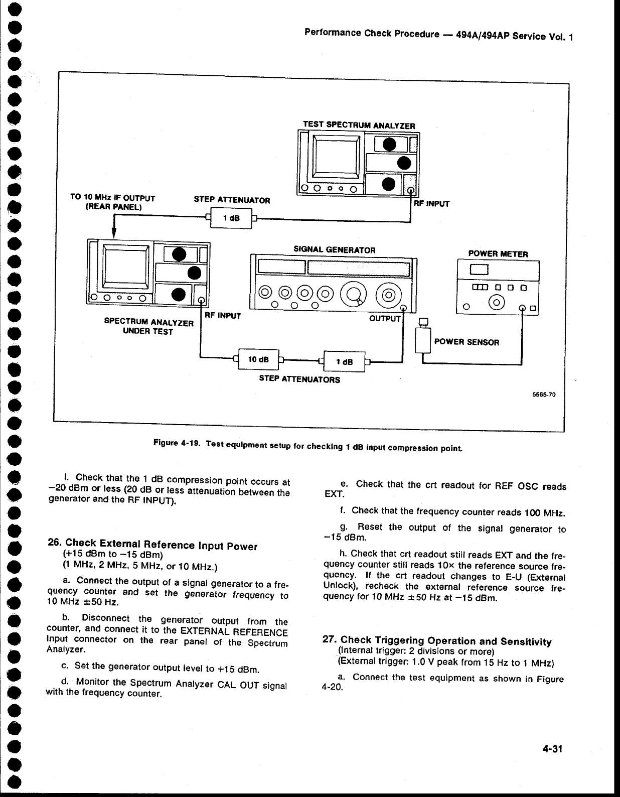
Check
that
the
1
dB
compression
point
occurs
at
-20
dBm
or
less (20
dB
or
less
attenuation
Oetween
the
generator
and
the
RF
INPUT).
26.
Check
External
Reference
Input
power
(+15
dBm
to
-15
dBm)
(1
MHz,
2 MHz,
5
MHz,
or
10
MHz.)
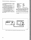
a.
Connect
the output
of
a
signal generator
to a fre-
quency
counter
and
set
the
generator
frequency
to
10
MHz
*50
Hz.
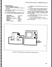
b. Disconnect
the
generator
output
from
the
counter,
and
connect
it
to
the
EXTERNAL
REFERENCE
Input
connector
on
the
rear panel
of
the
Spectrum
Analyzer.
c.
Set
the
generator
output
level
to
*1
5
dBm.
...d..
Monitor
the
Spectrum
Analyzer
CAL
OUT
signal
with
the frequency
counter.
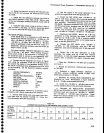
Performance
Check
procedure
-
4g4Al4g4Ap
Service
Vol.
1
e.
Check
that
the
crt
readout
for
REF
OSC
reads
EXT.
f.
Check that
the
frequency
counter
reads
100
MHz.
g.
Reset
the
output
of
the
signal
generator
to
-15
dBm.
h.
Check
that
crt
readout
still
reads EXT
and
the
fre_
quency
counter
still
reads
10x
the
reference
source
fre_
quency.
lf
the crt
readout
changes
to E_U (External
Unlock),
recheck
the external
reference
source
fre-
quency
tor
10
MHz
*S0
Hz at
-15
dBm.
27.
Check
Triggering
Operation
and Sensitivity
.(lnternal
trigger:
2
divisions or
more)
{External
trigger:
1.0
V
peak
from
.t
5 Hz
to
1 MHz)
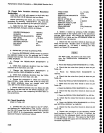
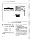
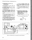
a.
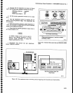
Connect
the
test equlpment
as
shown
in Figure
4-20.
TEST
SPECTRUM
ANALYZER
TO
10
tlHz
tF
OUTPUT
(REAR
PANEL)
STEP
ATTEI{UATOR
RF INPUT
SIGNAL
GENERATOR
SPECTRUTTI
ANALYZER
UNOER
TEST
RF
INPUT
OUTPUT
POWER
METER
@o@o@g@@
STEP
ATTENUATORS
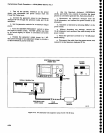
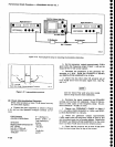
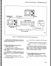
Flgure
4'19.
Test
equrpment
setup
tor
checkrng
1
dB input
compression
poinl
4-31


