


t
I
a
o
o
o
o
o
o
o
t
a
o
o
o
a
o
a
a
a
o
a
o
o
a
I
a
o
o
o
o
o
o
o
o
I
t
I
o
O
a
a
I
t
Performance
Check
procedure
_
4g4Ll4g4Ap
Servlce
Vol.
1
(4)
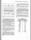
Check
that
amplitude
deviation
from
the
100
MHz
reference_does
not,*.""J-*i.s
dB.
Atso
check
that
flatn€ss
is
within
*1.5
dB.
c.
Connect
the
CAL.OUT
signat
to
the
RF
tNpUT,
and
perform
the
<Btue-SHIFT>
CAf-
iouiin".
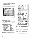
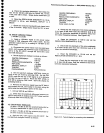
15.,Chec_k
Display
DVnamic
Range
and
Accuracy
(99
jB._il
_10
dB/DtV
moOe,-wirr
in-accuracy
or
:!1.0
dB/l0
dB
to^-a
maximum
cumulative
error
of
*2.0
dB
over
the
g0
dB
window;
rO
Oe-in
2
dBlDtV
rnode
wfth
an
accuracy
of
*0.4
ABpia
to
a
max_
imum
cumulative
enor
of
*1.0
Oe'ovei
the
16
dB
window;
Lin
mode
is
15%
ot
fuff
ica[l-'
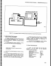
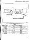
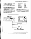
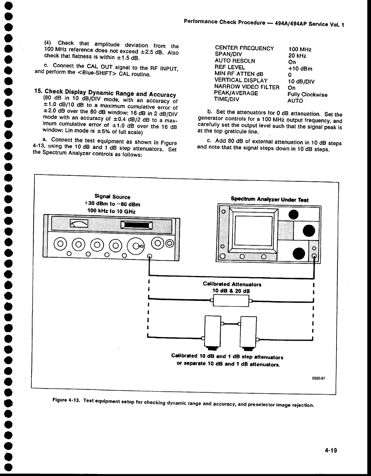
a.
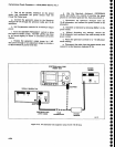
Connect
the
test
equipment
as
shown
in
Figure
4-13-,
using
the
lOdB
and
1'dB
siep"ti"nrutorr.
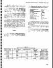
S"t
the
Spectrum
Analyzer
controls
as foilows:
b.
Set
the attenuators
for
O dB
attenuation.
Set
the
generator
controls
for
a.
100
MHz
output
frequency,
and
carefully
set
the output
level
such
ttrai
tne
signat peak
is
at
the
top
graticule
tine.
c.
Add
80
dB of external
attenuation
in
10
dB
steps
and
note
that
th€
signal
st€ps
down
in
10
dB
steps.
CENTER
FREQUENCY
sPAN/DtV
AUTO
RESOLN
REF
LEVEL
MIN
RF
ATTEN
dB
VERTICAL
DTSPLAY
NARROW
VIDEO
FILTER
PEAK/AVERAGE
TrME/DtV
100
MHz
20 kHz
On
*10
dBm
0
10
dB/DtV
On
Fully
Clockwise
AUTO
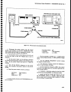
Signaf
Source
*30
dBm
to
-80
dBm
100
kHz
to
10
GHz
Specfrum
Analyzer
Under
Ted
Calibraled
Altenuators
10dB&20d8
Calfbrated
1O
dB
and
1 dB
step
ailenuators
or
separate
10
dB
and i
dB
attenualors.
Figure
4-13'
Test
eguipment
s€tup
for
checking
dynamic
range
and
accuracy,
and
preserecror
image
fejection.
4,19