


Malntenance
-
494A/494Ap
Servlce
Vol.
1
f. lf
the fuse
does not
open
and the
vottage
is still
absent,
it indicates
the trouble is
the
power
Supply.
(E)
g.
lf the voltage
from
a current
limited
supply
is
absent
or low,
the
problem
could
be the supply,
or cir-
cuits
the
supply
furnishes
may
be
drawing
excessive
curr€nt.
Turn
the
POWER
ofr,
then disconnect
the
suspect assemblies
or modules
from
the supply and
re-measure
the voltage;
or, remove
the
power
Suppty
from
the
instrument
and
measurE
the unloaded
voltagei
on
the Power
Supply
connector.
(1)
lf the supply
voltage
is correct
with assembty
or
module removed,
or
when
the
voltage
with
th€
power
supply
removed
is
normal,
the circuits
this
supply
furnishes
are causing
the
problem.
(E)
(2)
lf
the voltage
for
the
unloaded
supply
voltage
is
still
inaccurate,
the
power
supply
is
defective.
(g
TUNING FAILURE
-
1ST
LO
The 1st
LO
is set
by
a
combination
hardware/software
loop.
There
are
two
distinct
hardware
blocks
to the loop:
the
block
that measures
the oscillator
frequency
and
the
block that
sets
the
oscillator
to
frequency.
The
microprocessor
system
closes
the
loop
by det€rmining
how
much
the
oscillator
rnust
b€ tuned
to set
the
desired frequency.
The
microprocessor
indirectly
counts
the 1st
LO,
tunes
it as
needed, and
counts
again.
The
l st LO Tuning
Failure
error
message
is
displayed wh€n
the
lst LO has not
been set
correcuy
after a
number
of
iterations. The number of
times the
1st
LO is counted
and
tuned
varies with instrument
set-
tings.
The
l st LO
Control
Diagnostic Aid
displays data
on
the
crt
screen which can
be used to determine which
part
of
the
loop has
failed.
To display this data,
press
<BIUE.SHIFT>
PULSE STRETCHER
and
#3. th6n
select
#1.
The
first
two
lines
list
the
voltage to b€ exp€cted at
the
output
of
the
lst LO s€ction
of
the
Center
Fre-
quency
Control
and
the
voltag€
across the sense
resis-
tor
of
the
l st
LO Driver. The nominal values are based
on the
Desired
lst
LO Freq and
the
nominal
tuning
sen-
sitivity of
the
oscillator.
The DAG
Set
values
are
based
on the setting
of
the
lst
LO
tuning DACs.
The
DAC Set
values can
differ
from the Nominal
values
because the
system cannot be
exactly
calibrated,
tbe tuning sensitivity
of the
oscillator
is
possibly
not its nominal
value, and the
DACS will
be
moved in
an attempt
to
set
the
oscillator.
o
a
o
o
o
o
o
o
o
a
o
I
t
o
o
o
o
o
I
I
a
t
o
a
o
a
o
a
o
I
o
o
a
o
a
I
a
o
o
o
o
o
o
a
a
The
-17
V..:upPty
is
nol
monitored.
by trre
Power
supply
status cirouit nor
does it
have a
iest
point
on
the z-axis
board,
It this
suppty
rails,
the
cooling
fan
wilt
not
tun.
The
fsn will
atso not
run
it
tre
im5ient
tempe.ature
is tow.
The
-17
v
suipty witt
probably
affect other
suppliei ai
weil.
6-8
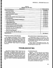
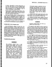
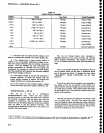
Table
6-3
POWER
SUPPLY
RANGES
Supply
Range
Test Polnt
Circult
Protecton
+300
v
+100
v
+17
V
15V
+9V
+5V
-5V
-7V
-15
V
-17V8
Gnd
280 V
to 310
V
95Vto105V
10.8
V
to 18.6
V
14.85 V
to 15.15
V
8.5
V
to 10.5
V
4.8
V
to
5.2 V
-4.8
V
to
-5.2
V
-7
V
to
-8.5
V
-14.85
V
to
-15.15
V
TPl052
TPl048
TPl047
TPr046
TPl011
TPl044
TPl036
TPl037
TPt035
TPl034
Fuse (F1033)
Fuse
(F1035)
Fuse
(F2013)
Current limit
Fuse
{F1014
Curent limit
Gurr€nt limit
Fuse (Fl013)
Current limit
Fuse (F3038)
Ground Refer€nce