


Malntenance
-
494A/494Ap
Servlce
Vol.
1
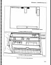
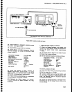
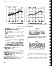
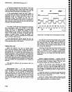
Figure
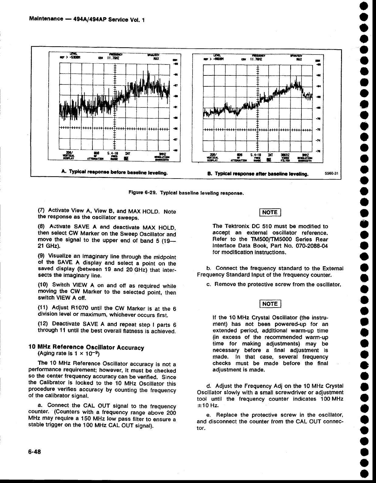
6-29.
Typlcal
basellne
teveling response.
o
o
o
a
o
o
o
t
o
t
o
o
o
I
t
o
o
o
o
I
a
o
o
o
o
I
a
o
o
t
t
a
o
o
o
a
o
o
o
o
o
I
o
a
(7)
Activate
View
A,
View
B, and
MAX
HOLD.
Note
the
response
as
th€
oscillator
sw€eps.
(8)
Activate
SAVE
A
and
deactivate
MAX
HOLD,
then select
CW
Marker
on
the
Sweep
Oscillator and
r_noye
the signal
to
the upper
end
of
band
S
(19_
21 GHz).
(9)
Msualize
an
imaginary
tine
through
the
midpoint
of
th€
SAVE
A
display
and
select
a
point
on
the
saved
display (between
t9
and
20
GHz)
that inter_
sects the
imaginary
line.
(10)
Switch
VIEW
A on and
off
as
required
white
rnoving
the
CW
Marker
to
the s€lected
point,
then
switch MEW
A ofi.
(11)
Adjust
R1070
until the
CW
Marker
is
at the
6
division
level
or
maximum,
whichEver
occurs
first.
(12)
Deactivate
SAVE A
and
repeat
step
I
parts
6
through
11
until
the
best
overall
flatness
is achieved.
10 MHr Reference
Oscillator
Accuracv
(Aging
rate
is 1
x
10-e)
The 10 MHz
Reference
Oscillator
accuracy
is
not
a
performance
requirement;
however,
it
must
be checked
so
th€
center
frequency
accuracy
can
be verified.
Since
the
Calibrator is
tocked
to the
10
MHz
Osciilator
this
procedure
verifies
accuracy
by counting
the frequency
of
the
calibrator
signal.
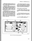
a.
connect
the
cAL
ouT signal
to
the
frequency
counter.
(counters
with
a frequency
range
above 20i)
MHz
may require
a
150
MHz low
pass
filter
to €nsure
a
stable
trigger on
the
100
MHz
CAL
OUT signat).
6-48
The Tektronix
DC
510
must
be
modified
to
accept an external
oscillator
reference.
Refer
to the TM500ffM5000
Series Rear
Interface Data
Book, Part
No.
070-2088-04
f
or
modification
instructions.
b.
Connect
the frequency standard
to the
Extemal
Frequency
Standard lnput
of
the
frequency
counter.
c.
Remove
the
protective
screw
from
the oscillator.
lf the 10 MHz
Crystal
Oscillator
(th€
instru-
ment) has not
been
powered-up
for
an
extended
period,
additional
warm-up
time
(in
excess
of
the
recommended warm-up
time tor making adjustments)
may be
necessary
before
a
final
adjustment is
made. ln
that
case,
several
frequency
checks must
be made before the final
adjustment is
made.
d. Adjust
the
Frequency
Adj
on
the
10 MHz
Crystal
Oscillator
slowly
with a small
screwdriver
or
adjustment
tool
until
the
frequency
counter
indicates
100
MHz
*10
Hz.
e. Replace
the
protective
serew in
the
oscillator,
and
disconnect the
count€r
from the CAL OUT
connec-
tor.
+
+
+
ll
ifl
I
td
II
lh t,l['r
tflru.d
fl
||'
't
VI[
!|'|n
I
'll
I
ll
n
{
{
{t
{
{l
-
..-
4
-a
s.+tc
ltrr
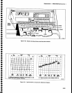
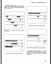
A TYptcrl
roapoNc
betore
baceline
lcveting.
B.
Typlcrl
rlrpo€e
aftcr
barcline lcvcling.
car ll-tqz
rl,,
rl.
A
rr'
IJ,
$
f
lh
ft
'I
hh
Fr
at oE
5.
ruTrcr.
t
n
-
-
I
-
-
-tt
-?l
-7a
-I
*tr
rD
t:!,la