


Adiustment
Procedure
-
494A/4g4Ap
Service
Vot. 1
10.
Adjusf
Calibrator
Output
Level
(R1041
on
the
100
MHz
Osc and
3rd
Converter
board)
The calibrator
output
level is
matched
to a
known
reference.
A
power
meter
is
used
to
verify
the
output
level
of
the
reference
sig_
nal
generator.
Harmonics
of
th€
signal gen_
erator
must
be
greater
than 40
dB
down
from
the fundamental.
a. Apply
a 100
MHz
signal
from
the
signal g€nera_
tor to the
power
meter
through a
3 dB
attenuator.
Set
the
generator
output
level
for
a
reading
of
-20
dBm
on
the
power
meter.
This
sets
up a reference
signal
for
adiusting
the
calibrator
output
level.
b.
Disconnect
the
power
meter
from
the signal
gen-
erator,
and
connect
th€ refence
signal
(from
the
genera-
tor) to
the
test
spectrum
analyzer
RF INPUT
using
the
same
cable
that was used
to
set
the
reference
signal.
c.
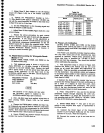
Set the test
spectrum
analyzer
controis
as
fol_
lows:
11. Adjust
lF
Gain
(Rl015
on
the 110
MHz
Amptifier
board)
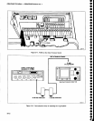
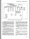
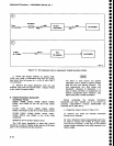
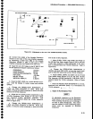
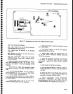
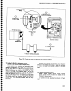
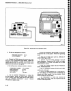
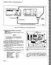
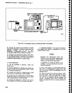
a. Test
equipment setup
is
shown
in Figure
5-20.
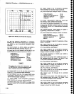
SEt thE
RESOLUTION
BANDWIDTH
tO
1 MHZ,
REF
LEVEL
to
-20
dBm,
and VERT
DISPLAY
to
2
dB/DtV.
Apply a
-25
dBm,
110
MHz
signat,
through
step
attenuators,
to
the
input
(J365)
of
the 110 MHz
fitter.
b.
set
the
step
attenuators
for
0 dB. set the
signal
generator
frequency
{or maximurn
amplitude
display.
With
-25
dBm input
the
signal
level
shoutd be
7
divi-
sions or
more.)
Set
the
generator
output
for a
7
divi-
sion signal
reference
level.
c.
Remove
the
110
MHz
signal
from
the
110
MHz
filter
and
reconnect
P365.
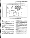
d. Set
the
step
attenuators for
21
dB attenuation
and
apply
the 110 MHz
signal
to
the input
(J321)
of
the
'110
MHz lF amplifier (Figure
5-20).
e.
Adjust
R1015,
110
MHz lF
Gain,
for a
disptay
amplitude
that equals
the
seven
division reference
set
in
part
b.
f. Remove
the
110
MHz
signal and
reconnect P321.
Apply
the cAL
ouT
signal
to the
RF |NPUT.
set
the
Spectrum
Analyzer controls as
follows:
FREQUENCY
100 MHz
FREQ
SPAN/DIV 100
kHz
RESOLUTION
BANDWIDTH
100
kHz
REF LEVEL
-20
dBm
VERT]CAL
DISPLAY
2 dB/DIV
g.
Set the front
panel
AMPL
CAL
fully counterclock-
wise
and
readjust Rl015
(110
MHz lF
Gain)
for
5 divi-
sions of
signal.
(lf
this
cannot
be
achieved,
it
indicates
excessive loss through the front end.)
h.
Adjust
the
AMPL
CAL
for a full
screen
signal.
AMPL
CAL
adjustment
should
now have 6 dB down
range
and
6 dB
or more up
range.
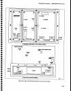
Two
variable
capacitors,
C1054
and C2047
on
the
110
MHz
lF
board, do not
require
adjustment
during
calibration.
These
adjustments
require return loss measure-
ment which
is a
maintenance and repair
function.
o
o
O
o
O
o
o
o
a
a
a
a
o
o
o
o
a
o
o
o
o
o
o
o
o
o
o
o
I
o
O
o
o
o
a
o
a
o
a
o
o
o
FREQUENCY
FREQ
SPAN/D|V
RESOLUTION
BANDWIDTH
REF
LEVEL
MIN RF
ATTEN
VIEW
A and
VIEW B
PEAK/AVERAGE
TrME/DtV
TRIGGERING
100 MHz
100 kHz
1
MHz
-18
dBm
0dB
On
Fully
Counterclockwise
AUTO
AUTO
d.
Set
the test spectrum
analyzer
Verticat
Display
factor
to the
A A mode
by
pressing
FINE.
Set
the
REF
LEVEL
such
that
the
top of
the
signal
is on
a
graticule
line
near
the
top
of
the crt.
Reset
the
REF
LEVEL
to
0.00
dB
by
pressing
FINE
twice.
Store
the
display by
activating
SAVE
A.
e.
Remove
the
r€ference
signal
from
the
RF
INPUT
and
connect
the cAL
oUT
signal
in its
place,
Tune the
CENTER
FREQUENCY
controt
to
atign
the
CAL
OUT
signal
with
the
SAVE
A
disptay.
f.
Adjust
Cal
Levet
R1041,
in
the
3rd converter
(#2
in Figure
5-20) for
no
displacement
between
the
CAL
OUT
signal
and
the reference
(VIEW
B and
SAVE
A
displays).
5-20