o
I
t
I
I
I
o
I
o
t
o
t
o
o
o
o
o
a
o
a
o
a
o
o
t
a
I
o
t
t
o
I
a
o
o
t
t
3
o
o
o
a
I
t
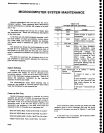
Microcomputer
System
Test
.The
microcomputer
system
test
is
chosen
by setting
switch
#8
ctosed
and
switch
#7
ogen
in
S1O6O.
fni
display
is
inoperative
while
this
test
is
being performed.
The
microcomputer
reports
th€
t€st
results
via
the
LEDS
on
the
GplB
board
rather
than on
the
GRT.
lf
a
prob-
lem
is encountered,
the
test
stops
and
the
problem
is
indicat€d
by
one
of
the
LEDS
on
itre
GptB
Ooard.
tf
no
problem
is
found,
the
system
test
takes
two
minutes.
,
The
system
test
_does
not
begin
normal
operation
after
the
test
is complete.
.. .
A.ddrelsgs
are
specified
as
hexadecimal
numbers
in
this
description.
l.
The
microcomputer
first
veriftes
the check
sum
of
the
system
ROM portion
of
U30S0
on
the
Memory
board.
The
check
sum
test
uses
no
memory
except
for
U3050.
The
correct
ROM
must
be
instailed,
the clock
on
the
Processor
board
must
be present,
and
the
microcomputer
system
bus
must
be
operating
correctty.
tf
the conect
check
sum
is
not
obtained,
the routine
halts
and
lights
DS1047
on
the
GplB
board.
lf
the
test
stops
but
does
not
tight
DS1O47,
and
everything
etse
seems
to be in
order,
the
Address
Bus
Test (desiribeo
later
in
this section)
should
be
performed.
2. Tl'rg
microeomputer
next
checks
part
of
the
pro_
cessor
interface
to
the
instrument
Uus'pln,
U1010,
on
the Processor
board.
lf
the
test
fails,
the
routine
stops
and
lights
DS1050
on
th€
GptB
board.
tf
the
test
succeeds,
the
processor
assumes
that
the
instrument
bus interface
is
working,
and
displays
PROCESSOR
SYSTEM
TEST,
PLEASE
WA|T.
on
the
trt.
3.
The
microcomputer
next
checks
RAM.
The
RAM
test contains
three parts.
The
first
part
performs
a
quick
test of all
non-battery
backed-up
RAM (U10.10
and
U3020
on
th€
Memory
Board).
The
microcomputer
loads
the
bit
paftern
01010101
into
a
RAM
tocation,
reads
the
location,
and
compares
what
is
returned
to
what
was
stored.
The
microcomputer
then
repeats
this
test with
the
pattern
10101010.
This
step
does
not
rely
on
the RAM
being
good
to
execute.
.
lf a reading
error
occurs,
the
microcomputer
stops
the
test and
pulses
LED
DSlO4g
on
the
GplB
board
tire
number
of
times
corresponding
to
the
RAM
that
failed
the test
(refer
to Table
6-11).
The
second part
of
the
test is
a
Moving
Inversions
test of
all
RAM (volatile
and
non-volatile).
This
test
assumes
that a
few
byes
of
the
RAM
are
good.
lf a
RAM
faits
this
test,
DS1O4g
on
the
Memory
board
is
pulsed
as
described
earlier.
Maintenance
-
4g4Ll4g4Ap
Service
Vot.
1
The
third
part
of
the test
is
similar
to
the
first part.
However,
the
memory
contents
are
allowed
to
reside
in
memory
for
thirty
seconds
before
being
read
back.
The
results
are
reported
via
DS104g.
4.
The
microcomputer
next
performs
a check
sum
test of
all
ROMs.
The
check
sum
stored
in each
ROM
is
compared
to the check
sum
formed
by the
successive
16-bit
spirat
sum
of
each
byte in
tne nOU,
starting
at
the
third location
in
the ROM.
The
ROM
number
co-ded
into
each
ROM will
cause
an error
if a
ROM
is installed
in
the wrong
location.
The
Tektronix
part
number
is
also coded
into
each
ROM.
lf
the
part
number
suffix
and its
complement,
which
are stored
in
th€
fifth
and
sixth
bytes of
the
ROM
header,
do not
read
as
complements,
the
microcom-
puter
assumes
that
no
ROM
is installed
and
does
not
attempt
the checksum
test.
lf
a
bad or
misplaced
ROM
is found,
the
microcom_
puter
pulses
DS1049
on
the
GplB
board N+1
times,
where
N
is
the number
of
the
ROM
in error
(e,g.,
a
bad
ROM
#3 will
cause
four
pulses;
refer
to Table
Gi2).
Missing
ROMs
are
reported
as
described in
part
6.
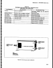
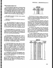
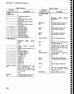
Table
6-12
TEST
ROM
0
1
2
3
4
5
6
7
I
9
10
11
12
13
14
15
16
17
ROM
Saakct
Board
DSl049
u3060
u3060
u1010
u1010
u1020
u1020
ul025
u1025
ul035
ul035
u301
5
u301
5
u3020
u3020
u3030
u3030
u3050
u30s0
A54
Memory
A54 Memory
456
GPIB
456
GPIB
A56 GPIB
A56
GPIB
A56
GPIB
456
GPIB
456
GPIB
A56 GPIB
456
GPIB
456
GPIB
A56
GPIB
A56
GPIB
456
GPIB
456
GPIB
A54 Memory
A54 Memory
1
2
3
4
5
6
7
I
9
10
11
12
13
14
15
16
17
6-51
Tabfe
6-11
u1010
u3020
ul030


