Performance
Check
procedure
-
4g4Al4g4Ap
Service
Vot.
1
f. Turn off
the
50 MHz
reference
on
the
power
rneter,
and
disconnect
th€
power
sensor
from
the
Power
Ref
Output
port.
-
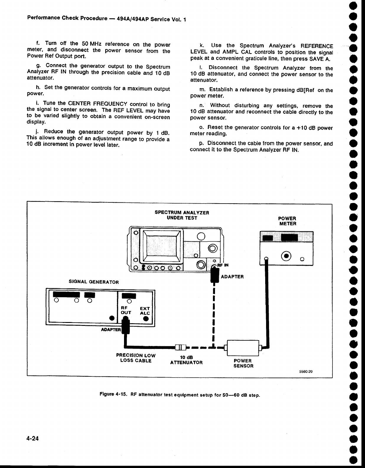
g.
Collect
the
generator
output
to
the
Spectrum
Analyzer
RF lN
through
the
precision
cabte
and
10
dB
attenuator.
h.
Set the
generator
controls
for a
maximum
output
power.
i.
Tune
the
CENTER
FREQUENCy
controt
to bring
the
signal to
center
screen.
The
REF
LEVEL
may
hav6
to be varied
slightly
to obtain
a
convenient
on-screen
display.
_-
j.
Reduce
the
generator
output
power
by 1 dB.
This allows
enough
of
an
adjustment
range
to
piovide
a
10
dB
increment
in
power
level later.
k.
Use
the
Spectrum
Anatyzer's
REFERENCE
LEVEL and
AMPL
CAL controls
to
position
tho signal
peak
at
a convenient
graticule
line,
then
press
SAVE A.
l. Disconnect
the
Spectrum Analyzer
from
the
10
dB
attenuator,
and
connect
the
power
sensor
to the
attenuator.
m.
Establish
a reference
by
pressing
dB[Ref
on
the
power
rnet€r.
n. Without
disturbing any settings,
remove
th€
10
dB
attenuator
and
reconnect
the cable
directly
to the
power
sensor.
o. Reset
the
generator
controls
for a
+10
dB
power
meter
reading.
p.
Disconnect
the cable from
the
power
sensor,
and
connect it
to the Spectrum
Analyzer
RF lN.
o
o
t
o
a
o
o
o
o
a
o
I
o
o
I
I
a
a
a
o
o
o
o
o
I
o
o
o
t
o
I
o
o
o
I
t
t
a
a
o
o
a
I
I
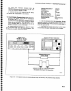
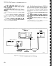
SPECTRUM
ANALYZER
UNDER TEST
POWER
METER
SIGNAL
GENERATOR
I
I
I
I
I
I
I
--J
PRECISION
LOW
LOSS
CABLE
10
dB
ATTENUATOR
POWER
SENSOR
4-24
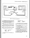
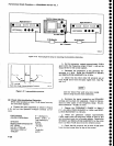
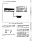
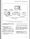
Figure
4-15.
RF
attenuato.
test
equipment
setup
for
50-60 dB
step.


