


Maintenance
-
494A1494Ap
Service
Vot.
1
_
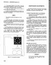
Check
the
freguency
by noting
the
reading
on
the
frequency
counter.
lf
above
729.900
MHz,
the
stub
must
be
lengthened.
Solder
a
bridge
across
the cut
"q
r.e"!99\
frequency.
Nominal
frequency
for an
uncut
stub
is 710
MHz.
f.
Shorten
the line
so
the
frequency
is
near
723.500
MHz.
For example:
The
frequency
difference
between
the
desired and
thE
actuat
divideci
Oy
Z
Unz,
equals
the number
of
minor
divisions
from
thE line
end
for
the
new
cut.
Make
a cut
across
the
line and
check
that
the
new
frequency
is
between
723.100
MHz
and
723.900
MHz.
Repeat
as
necessary.
g.
Cover
the 719
MHz
osciltator
cavity
with
the
g29
MHz
Converter
cover,
press
down
to ensure good
shielding,
and
note
the frequency
readout
of
the
counter.
Frequency
should
fall within
723.600
MHz and
724.400
MHz.
h.
Reconnectp2S4
(100
MHz)
andp237
(2i82
MHz)
and confirm
that
phase
lock
is
operating
by noting
thai
the
voltage
on
Tp1011
is
between
O.7SV
and
7.5V.
This
completes
the
adjustment
of
the
71gMHz
Lo.
Replace
the cover
and
reinstall
the
g2g
MHz converter
assembly.
4.
829 lr/lHz
Coaxial
Band-pass
Fitter
Adjustment
This
procedure
is
necessary
if
the
position
of
one of
the
variable
capacitor
loops (tabs)
has
been altered,
changing
the
bandpass
characteristica
of
the
filter.
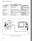
a. Test
equipment
required:
Spectrum
analyzer
with
tracking
generator
(such
as
a TEKTRONIX
49X-Series
Spectrum
Analyzer
with
TR
503
Tracking
Generator,
or
7L,t4
with
i TR
502
Tracking
Generator);
Frequency
Counter (such
as
a
TEKTRONIX
DC 510
Counter
with
a
Dp
501
pres_
caler);
and
a
Beturn
Loss
Bridge (such
as
a Wiltron
Model62BF50.)
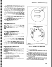
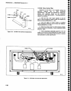
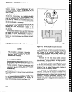
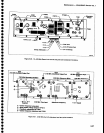
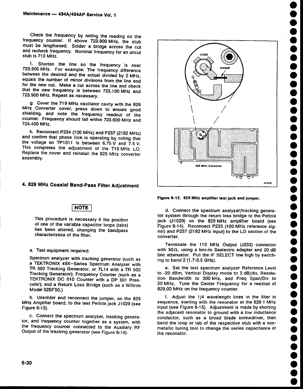
b.
Unsolder
and
reconnect
the
jumper,
on the
g2g
MHz
Amplifier
board,
to the
test
peltola
jack
J1029
(see
Figure
6-13).
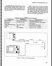
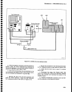
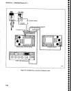
c.
Connect
the spectrum
analyzer,
tracking
genera-
tor, and
frequency
counter
together
as
a system,
with
the frequency
counter
connected
to
the
Auxiliary RF
Output of
the
tracking
generator
(see
Figure
6-14).
-
\
\
Figure 6-13. 829
MHz
ampllfier
test
iack
and
iumper.
d.
Connect the spectrum
analyzerltracking
genera-
tor system through
the return
loss
bridge to the
Peltola
jack
(J1029)
on
the
829MHz amplifier
board
{see
Figure
6-14).
Reconnect
P235
(100
MHz
reference
sig-
naf) and P2g7
(2182
MHz input)
to
the LO
section
of
the
converter.
Terminate
the
110
MHz
Output
(J2
21
connector
with
50o,
using a
bnc-to
Sealectro
adapter
and 20
dB
bnc attenuator. Pull
the
lF
SELEGT
line
high
by
switch-
ing
to
band 2
(1.7-5.5
GHz).
e.
Set
the
test spectrum
analyzer
Reference
Level
to
-20
dBm,
Vertical
Display
mode
to
2
dBldiv, Resolu-
tion
Bandwidth to
300
kHz,
and
Freq
Span/Div to
20
MHz. Tune
the Center Frequency for
a readout of
829.00 MHz
on
the frequency counter.
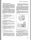
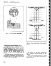
f. Adjust the 114 wavelength
lines
in
the
filter in
sequence, starting
with
the
resonator
at
the 829 1
MHz
input
(see
Figure 6-15),
Adjustment is
made
by
shorting
the adjacent resonator
to
ground
with a low inductance
conductor, such
as a broad
blade
screwdriver,
then
bend
the
loop
or
tab
of
the respective
stub with
a
non-
metallic
tuning tool to
change
the
series
capacitance
of
the resonator.
o
a
o
a
a
o
a
o
o
a
a
a
o
a
o
a
o
o
o
O
o
o
o
o
o
o
o
o
o
o
O
o
o
o
o
o
o
o
o
o
o
o
o
o
6-30