


Malntenance
-
494A1494Ap
Servtce
Vol.
1
5. Measure
the 2nd
LO
Tune
Volts
at
Tp1044
on
the
Center Frequency
Control
board.
a.
lf
the
2nd
LO
tuning
vottage
is
within
200
mV of
the DAC
SEt value,
measure
the 2nd
LO frequency
at
the
front-panet
2ND
LO
Output
connector.
(1)
lf
the
measured
frequency
does
not
agree
with
the internally
counted
roadout.
the couhter
board is
probabty
at
fautt.
(E)
(2)
lf
the
frequency
agrees
with
the
Counted
value,
measur€
the
mixed
down
frequency
at
the
cable
going
to
p513
on
the
Count€r
board.
This
frequency
should
equal
the sum
of
th€ Desir€d
Offset Freq
and
the
Desired
2nd
LO
Freq,
less
the measured
2nd
LO
frequency.
(a)
lf
this
freguency
19
present,
measure
the
2182MHz
oscillator
tuning
voltag€
on
the
feedthrough
capacitor
CZaO}
between
the
16-20
MHz
phase
Lock
circuit
and
the
2tg2
MHz
Microstrip
Osciltator
in
the
21g2 MHz
Phase
Locked
2nd
LO Assemblv.
The
nor-
mal
range
of
this
voltage
is
0V
to
-12.5V.
With
the
phase
locked
loop
unlocked,
this
vottage
wiil
probably
be stighuy
outside
one
end
of
the
range.
(0
tf
the absolute
value
(magnitude)
of
the
tuning
voltage
and
the
oscillator
fre_
quency
are
ofi
in
the same
direction
from
the
centers
of
their respective
ranges
[6
{-6)
V and
2182
MHz
,
the Microstrip
Osciltator
has
probably
faited.
(E
(ii)
tf
th€
absotute
value (magnitude)
of
the
tuning voltage
and
the
oscillator
fre-
quency
are
off
in
the opposite
direction
from
the center
or
their
respective
ranges
16
(-6)
V and
2i
82 MHz
,
some
other
part
of
the lock
loop,
besides
the
Microstrip
Oscillator, has
probably
failed.
(E)
(b)
lf
the
mixed-down
frequency
is
absent,
either
the 22OO
MHz
Reference,
the
2182MHz
Microstrip
Oscillator
or
the
22AA
MHz
Reference
Mixer probabty
has
faited.
(E)
b. lf
the
tuning
vottage
is
not
within
200
mV
of
the
DAC
Set
value,
the Center
Frequency
Control
board
probably
has
faited.
(E)
PHASE
LOCK
FAILURE
-
1ST
LO
The following procedure
assumes
that
the oscillator
is at
the conect
frequency,
so
the
probtem
must
be in
the
phase
lock
system.
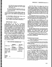
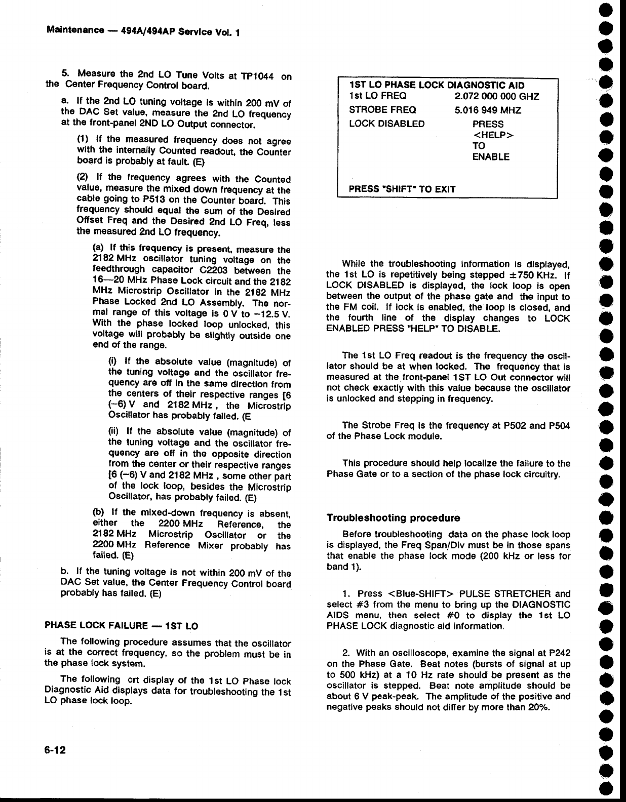
The
following
crt
display of
th€
lst
LO
phase
lock
Diagnostic
Aid
displays
data
for
troubteshooting
th€
1st
LO
phase
lock
loop.
lST LO PHASE
LOCK DIAGNOSTIC
AID
lst LO FREQ
2.A72000
000 cHZ
STROBE
FREQ
5.016 949 MHZ
LOCK DISABLED
PRESS
<HELP>
TO
ENABLE
PRESS'SHIFT'TO
EXIT
While the
troubleshooting
information is
displayed,
the lst
Lo is
repetitively
being
stepped
*750KH2.
lf
LOCK
DISABLED
is display€d,
the
lock
loop
is
open
between the
output
of
the
phase gat€
and
the input
to
the FM
coil.
lf
lock is enabled,
the loop is
closed,
and
the fourth line of
thE display
changes
to LocK
ENABLED
PRESS
"HELP"
TO
DISABLE.
The lst
LO
Freq
readout
is
the
frequency
the
oscil-
lator
should be
at
when locked. The frequency
that
is
measured at
the front-panel
1ST LO Out connector
will
not
check exactly with
this
value
because
the
oscillator
is
unlocked
and
stepping in frequency.
The Strobe
Freq
is the frequency
at
P502 and
P504
of
the Phase Lock
module.
This
procedure
should
help
localize the failure
to the
Phase
Gate
or
to
a
section of
the
phase
lock
circuitry.
Troubleshooting
procedure
Before troubleshooting
data
on
the
phase
lock loop
is
displayed,
the
Freq
Span/Div
must be in
those
spans
that
enable
the
phase
lock mode
(200
kHz or
l€ss for
band 1).
1. Press
<BIue-SHIFT>
PULSE
STRETCHER
and
select #3 from
the menu to
bring
up
the
DlAGNosTlc
AIDS
menu, then select #0
to
display the
1st
LO
PHASE
LOCK diagnostic aid
information.
2. With an
oscilloscope,
examine the
signal atP242
on
the
Phase Gate.
Beat notes
(bursts
of signal at
up
to 500 kHz)
at a
10 Hz rate should'be
present
as th€
oscillator
is stepped.
Beat note
amplitude
should be
about
6
V
peak-peak.
The
amplitude of
the
positive
and
negative
peaks
should
not
differ by
more
than
2Oh.
6-12