


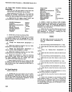
Performance
Check
procedure
-
4g4Al4g4Ap
Service
Vol. 1
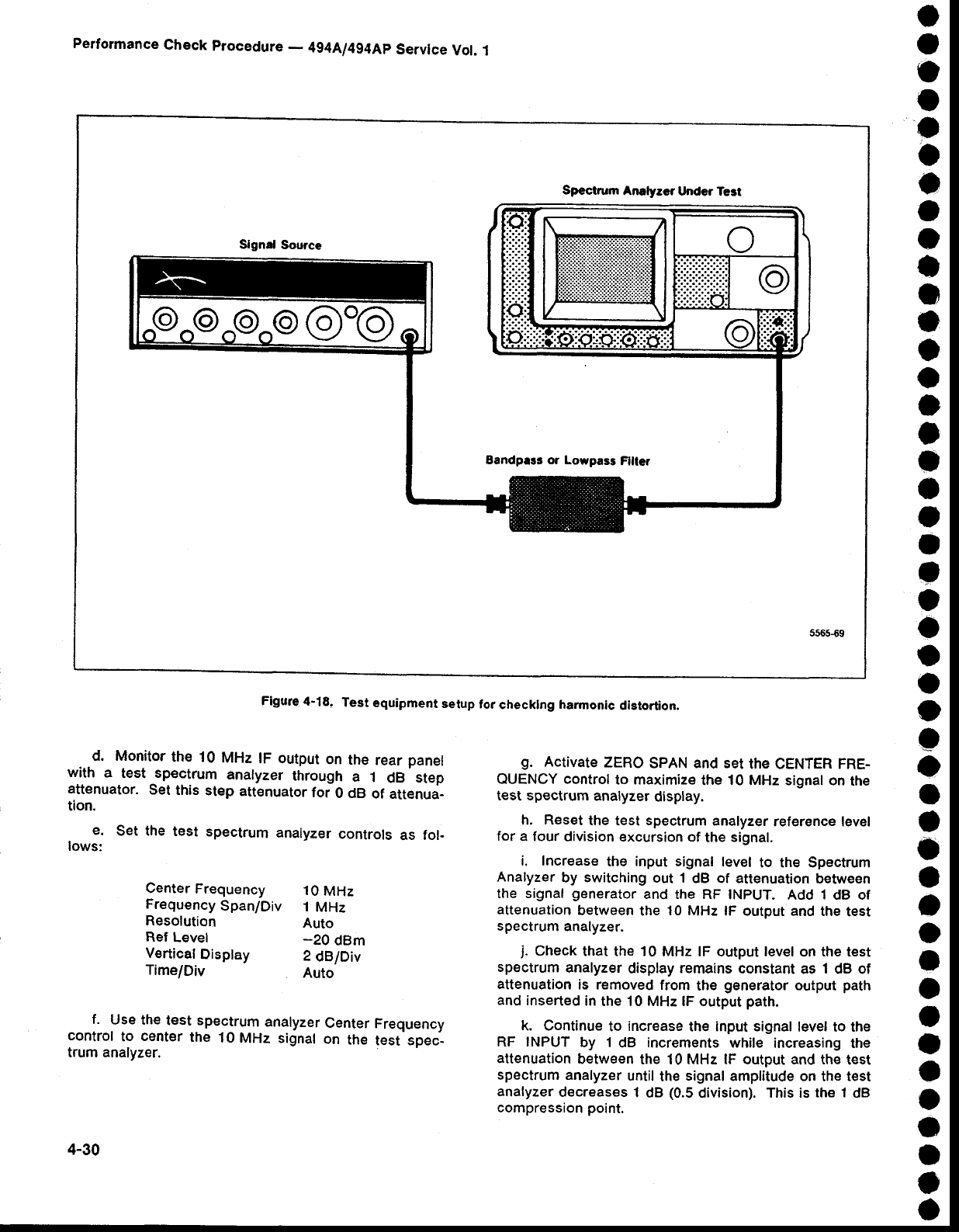
Spectrum
Analyeer
Under Test
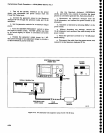
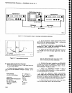
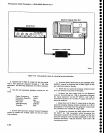
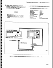
Figure
4-18.
Test
equipment
setup
lor
checklng
harmonic
distortion.
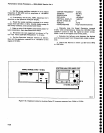
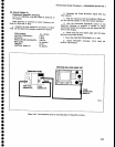
d.
Monitor
the
10
MHz
lF output
on
the
rear
panel
with
a
test
sp€ctrum
analyzer
through
a
1
dB
step
attenuator.
Set
this
step
attenuator
for
0 clB
of
attenua-
tion.
e.
Set the
test
spectrum
analyzer
controls
as
tol-
lows:
Center
Frequency
10
MHz
Frequency
Span/Div
i
MHz
Resolution
Auto
Ref
Levet
_20
dBm
Vertical
Disptay
2
dB/Div
Time/Div
Auto
f.
Use the
test spectrum
analyzer
Center
Frequency
control
to
cent€r
the
10
MHz signal
on
the
test spec-
trum analyzer.
g.
Activate
zERo
spAN and set
the CENTER FRE-
OUENCY control
to maximize
the
10 MHz
signal on
the
test spectrum
analyzer
display.
h. Reset
the
test
spectrum
analyzer
referEnce level
for
a four
division excursion
of
the
signal.
i. Increase
the input signal
level
to the Spectrum
Analyzer
by switching
out 1
dB of attenuation
between
the signal
generator
and the RF
INPUT.
Add
1
dB of
attenuation
between
the
10
MHz lF output and
the
test
spectrum
analyzer.
j.
Check
that the 10
MHz lF output level on the test
spectrum
analyzer
display
remains
constant
as
1
dB of
attenuation
is removed
from
the
generator
output
path
and
inserted
in
the 10 MHz lF output
path.
k. Continue
to
increase
the
input signal
level to the
RF INPUT
by 1
dB increments while
increasing the
attenuation
between
the 10 MHz lF output and the
test
spectrum
analyzer
until
the
signal
amplitude on
the
test
analyzer
decreases
1
dB
(0.5
division). This is
the 1
dB
compression
point.
4-30