


Adluctment
Procedure
-
4g4A/4g4Ap
Servtce Vot.
1
o
o
o
o
o
o
o
)
o
o
o
o
o
o
;
a
o
o
I
I
o
O
o
o
t
o
o
O
o
o
a
o
)
o
o
o
t
o
I
o
a
a
a
o
Table
5-l
EOUIPMENT
REOUIRED
Equlpment
or Test
Flxture
lsolation
Transformer
Att€nuator (3
dB
miniature)
Autotransformer
Multimeter
Dc
Block
Adapt€r
(Sealectro
male
to
male)
Adapter (bnc
female
to
Sealectro
male)
Three
Extension
Cables
(Sealectro
female
to Seal€ctro
male)
Adapter
(bnc
to Sealectro)
Adapter
(bnc
female
to
sma
male)
Cable
(20"),
Tip
Ptugs
to
bnc
CoaxialCable
(8)
50 O Terminator
Screwdriver,
Tuning
Alignment
Tool
Screwdriver, Flat,
6" with
1/8,
Tip
Screwdriver,
Phillips
No.
1
Recommendatlon
and
Use
Stancor
G|S21000
Weinchel
Model
4M,
Tektronix
Part
No.
015-1053-00
General
Radio Variac Type
Wl0MT3
TEKTRONIX
DM 5O1A
or
DM
5O2A
Tektronix
Part No.
015-022140
Tektronix
Part
1
0i!-0098-00
Tektronix
Part No. 103-0180-00
Tektronix
Part No. 17$2902-00
Tektronix
Part No.
175-241240
Tektronix
Part No. 015-1018-00
Tektronix Part
No.
175-1178-00
Tektronix
Part No. 012-020&00
Tektronix
Part No.
011-0049-01
Tektronix Part
No. 003-0675-00
Tektronix Part
No. 003-0968-00
Tektronix Part No. 672-0865-01
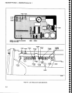
4.
Place
the
instrument
on the bench
and reconnect
the
power
cord.
Some
circuit
boards
or assemblies
must
be
removed
and
placed
on
extenders
to
gain
access
to
some
test
points
or adjustments.
When
this
is
done,
turn the
power
off
before
removing
the
assembly.
Allen
Wrenches (3),
3lgl,
5/il"
7lu
Service
Kit
(Extender
Boardsla
1:1
turns ratio
AND
AT
LEAST
500
VA
Frequency,
to 5
GHz;
connectors
5
mm
Capable
of
varying
line
vottage from
90
Vac
to
130
Vac
100
pV
to
350
Vdc
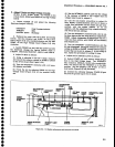
ADJUSTMENT
PROCEDURE
PREPARATION
Remove
the cabinet
as
follows:
1.
Set the
instrument
on its
face
or
front
panel.
2.
Loosen
the lour screws
through
the back rubber
feet.
3.
Pull
the cover
up and
off.
e
This kit is
pari
of the service
Kit
006-3286-01.
listed
in the Maintenance
section,
5-2