


Theory ol
Operaton
-
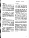
4g4A/494Ap
Service,
Vot.
1
R2
Rl
1ok
t,
I
20k
.
I
s1
4114122
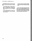
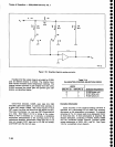
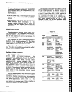
Flgure 7-23.
Simplified
digital-to-analog
convertGr,
o
o
o
o
I
a
o
o
o
o
o
o
o
o
o
)
a
o
I
t
o
o
o
a
o
o
o
o
I
I
o
o
o
o
o
o
o
o
a
o
o
o
o
o
Feedback for
the output
stage
is
provided
by R1056,
plus
an
internal resistor
in
U1042.
The
internal
feed-
back resistor
ensures
better
temperature
tracking. The
internal
resistor
provides
a
gain
slightly
less
than
unity;
R1056 increases
the stage
gain
and
permits
gain
caii-
bration,
as described
below.
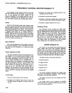
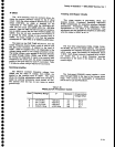
One-of-four
decoder,
U4025,
uses
data bits DBg
and DB4
lines from
U2015,
to control
three sections
of
a
quad
FET switch,
U3025. (RC
circuit
inputs
of each
FET control line
filter
out
noise
from
the
digital
circuits.)
The
code
is
exclusive;
i.e.,
only
one FET
is switched
on
at a
time. See Table
7-14
lor
a listing
of
the codes.
When
a FET is
switched
on,
it connects
a
calibration
adjustment
potentiometer
to the
summing
node
of
the
operational amplifier.
Adiustment
Rl065
sets
the 1st LO
tune
coil
swE€p,
R1071
sets
th€
1st
LO
FM coil
sw€€p,
and
R't
067
sets
the 2nd
LO span.
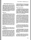
Table 7-14
CALIBRATION CONTROL
SELECTION CODES
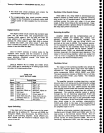
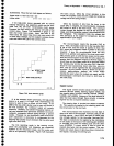
Decade Attenuator
Since accuracy
of
the digital-to-analog
converter is
specified
as
a
p€rcentage
of full scale,
the
accuracy
decreases as the attenuation is increased.
To
maintain
accuracy at'l./o, it is never
used
at an att€nuation
factor
of
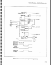
more than ten. lf more attenuation is required, the
decade
attenuator. consisting ol
K4072, K3075,
K3065
and
the connected divider network,
provides
further
swe€p
attenuation
of X0.01
,
X0.1,
and Xl .
See
Figure
7-24
tor a simplified circuit
diagram.
R1065
(main
coil)
Rl071
(FM
coil)
R1067
(2nd
LO)
7-66