


o
o
o
o
o
o
o
o
o
o
o
a
o
o
o
o
o
o
a
o
o
o
o
I
o
o
o
o
o
I
o
o
o
a
o
I
a
o
|
o
o
a
o
o
(1)
Press
<Btue-SHtFT>
PULSE
STRETCHEB
and
#0,
then
setect
either
the
lst
to reaoout
lmenu
item
#1)
or
the
lnd fg.readout
(menu
iteni
*e1.
I!9 _LO
frequency
wiil
be
displayect
on
the
crt
CENTER
FREQUENCY
readout
pbsition.
(2[fter
n-oting
the.freque^ncy
of
the
oscillator,
press
<Blue-SHtFT>
PULSE
STRETCHER
and
#0,
and
select
center
frequency
readout
to return
to
the
nor-
mal center
frequency
readout
mode.
Since
the
instrument's
power
is
usually
switched
on
and
off
during
troubleshooting,
the
ponJer-do*n
set-
tings,
that are
automatically
Ltored
in
register
0 of
Paltery-backed-up
memory,
lhout6
be
recalted
so
the
instrument
settlngs
and
operating
mode
dupticate
those
that
existed
when
th€ error
message
was
ginerat"d.
.
The
following,
describes
each
error
message
and
the
procedures
recommended
to
locate
the
problem.
POWER
SUPPLY
OUT
OF REGULATION
Any out-of-tolerance
voltage
will
cause
this
eror
m.?.":"g.e
to
be
displayed.
A
pow€r
suppty
status
circuit
within
the
power
supply
will
change
tne itatus
LED
on
the
Z-Axis
board
to
red,when
any
suppty
except
_17
v
changes
by
more
than 25%.
An
-error'message
will
be
also-
be displayed.
An
apparent
power
suppty
failure
can
be
produced
when
either
the supply
fails
or
a
circuit
demands
excessive
current
and
Of owi
L
protective
fuse
or
produces
a
current
limit
condition.
The
following
procedure
should
determine
those
voltages
that
are
out
of
range
and
whether
the failure
is
in
th6 supply
or
in a
circuit
outside
the
supply.
Troubleshooting
procedure
The
spectrum
analyzer
uses
a
high
eficiency pow€r
supply,
with
the
primJry
ground
potential
difierent
from
chassis
or
€arth
ground.
An
isolation
transformer,
with
a
turns
ratio
of
1:1
And
a
5OO
VA
minimum
rating,
should
be
used
between
the
power
source
and
the
spectrum
analyzer power
input
receptacle,
The
transformer
must
have
three-wire
input
and
output
connectors
with
a
through
ground
99!*99n
input
and
output.
-
S-tancor
GlS1000
is
an
€xample
of
a
suitable
transformer.
A
iump€r
should
also
be
con-
n€cted
between
th€
primary
ground
side
to
chassis
ground
(emitter
of
e2061
and
the
ground
t€rminat
of
the input
fitter
FL301).
Malntenance
_
4g4Ll4g4Ap
Servlce
Vol.
1
lf
the
power
supply
is
separat€d
from
the
instrument
and
operated
on
the
bench,
hazardous potentials
exist
within
the supply
for
several
seconds
after
power
is
discon_
nected.
This is
due
to the slow
discharge
of
capacitors
C6101
and
C61fi.
DS5112
(next
to
96111)
tights
when
the
potential
exceeds
80
V.
_ -
1.
Verify
that
the
power
supply
status
LED,
on
the
Z-Axis
board, is
red.
lf
the LED
is
green,
there
is
prob-
ably
a
failure
in
the
microprocessor
lnterface.
(E)
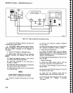
.2,
Measure
the
power
supply
voltages
at
the
test
points
on
the Z-Axis
board.
To access
ine
test
points,
remov€
the hold
down
cover
over
the
Sweep
and
Z-Axis
boards.
Hazardous
voltages
(900
V and
100
V)
are
present
on
the
Z-axis
board.
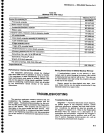
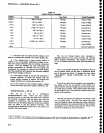
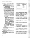
The
ranges
for
each
supply
are listed
in
Table
6€.
ThEse
are
tolerance
limits
which
are
much
tighter
than
the limits
used by
the
power
supply
sensing
circuit.
A
supply
that exceeds
these
limits
may
not
trigger
the
error
message
or
cause
the instrument
to
malfunction.
The
+15
V supply
is
adjustable
and
affects
the other
supplies.
Refer
to the
Adjustment
procedure
section
of
the
manual
for adjustment
information
if
a supply
is
iust
out
of
tolerance.
.
a.
lf all
supplies
are
within
limits
and
the
power
sup_
ply
status
LED is
r€d,
the
probtem
is
probably
in
the
power
supply
status
circuit
on
the
Z-Axis
board.
R1065
may
be misadjusted;
adjust
Rl065
to
see it
the
LED
changes
to
green.
lf
it changes,
set
R1065 at
the
center
of
the
'green'range.
(E)
b. lf
the
+17 V or
-17
V suppty
and
any
other
sup-
ply
or
supplies
are
inaccurate,
or,
if
both
the +9 V
and
+5 V
supplies
are
inaccurate,
the trouble
is likely
in
the
Power
Supply.
(E)
c.
lf
the
voltage
is high
(in
absolute
value),
the
trouble
is
probably
in
the Power
Supply.
(E)
d.
lf
the
voltage
from
a fused
supply
is inaccurate,
the trouble
is
probabty
in
the
power
Suppty.
{E)
e.
lf
the voltage from
a fused
supply
is absent,
it
indicates
the fuse could
be blown. To access
the fuses.
remove
the cover
at
the
top
left
hand corner
of
the
Power
Supply module (as
viewed
from
the front
of
the
instrument),
A blown
fuse
generally
indicates
that
one
of
the
circuits
that this
supply
furnishes
is
defective;
however,
a fuse
may
open
without an
overcurrent
con-
dition.
Replace
the
fuse and
try
again.
lf
the
fuse
opens,
the trouble is
definitely in one
of
th€
circuits
the
supply
furnishes.
6-7