


a
o
o
o
a
o
o
o
o
O
a
o
o
a
o
o
O
o
o
o
o
o
o
o
o
o
o
o
o
o
o
o
o
o
O
o
o
o
o
o
a
o
o
''
7.
Adjust
Log
Amptitier
(R1012,
R102S,
R1030,
R1037,
and
R.t060
on
the
Log
Amptifier
board)
Use
only
an
insulated
screwdriver
or
tuning
tool
to make
these
adjustments.
.
a.
Set
the
Log
Amplifier
correction
factors
to
zero
b_y
pressing (Bfue-SHtFT>
PULSE
STRETCHER
(DIAGNOSTIC
FUNCTTONS;
and
setecting
item
5
(DISABLE/ENABLE
USE
OF
CAL
FACTORS),
tnen
item
2
(SET
RESULTS
TO "UNCALED).
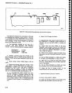
Remove
Leveler
Disable
plug
P3035
on
the
Video
processor
board
(Fig_
ure 5-1 1).
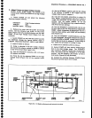
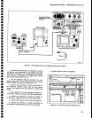
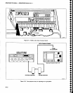
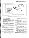
b.
Connect
the t€st
equipment
as
shown
in
Figure
5-12.
(P621
must
be
removed
in
order
to access
J621
on
the Log
Amplifier
board.
See
Figure
S_1g.)
Set
the
Spectrum
Analyzer
controls
as
follovis:
FREQUENCY
2MHz
FREO
SPAN/D|V
2MHz
AUTO
RESOLN
On
REF
LEVEL
-60
ctam
MIN
RF
AfiEN
OdB
VERT|CAL
DTSPLAY
1O
dB/DtV
TtMEiDtV
10
ms
c.
Center
the two
front
panel
LOG
and
AMPL
CAL
adjustments.
Set
the signat
generator
controls
for
a
10MHzl+6
dBm
output.
Set the
step attenuators
for
50 dB
of
attenuation.
d.
Position
the
display
at
a
graticule
reference
line
with
the vertical
POSITION
control,
then switch
the
REF
LEVEL
from
-60
dBm
to
-110
dBm
in
decade
steps.
e.
S€t the front-panel
LOG
CAL such
that
each
10
dB
step
equals
one
division.
f.
Reset
the REF
LEVEL
to
-20
dBm
and
tha
step
attenuators
for
0 dB attenuation.
Reset vertical position
to a
graticule
line if
necessary.
g.
Increase
the
attenuation
through
the step
attenuators
in
10
dB increments
to 50 dB.
_
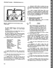
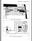
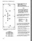
h-
Adjust
the Log
Gain,
R1037
(Figure
S-13)
so each
10
dB increment
of
attenuation
results
in one
major
divi-
sion
of
change
on
thE
display.
.
i.
Reset
vertical
position
by temporarily
removing
the signal
and setting
the
verticat
POSITION
control
to
position
the baseline
at
the
bottom
graticule
line.
Return
the step attenuator
to
0 dB. Display
should
be
full
screen (+6
dBm);
if
not, readjustJtrg*iglfial-gene@-
@
lzJ,r
rli,1
[v
i:"lllCrerh
j.
Adjust
Input
Reference
Level, R1012
(Figure
5-13)
for
minimum
amplitude
change
between the
10
dB/DlV
and
2
dB/DlV
displays
while alternately
switching
the
VERTICAL
DISPLAY
between
10
dB/DtV and
2 dB/DlV.
Adjustment
Procedure
-
494Ll4g4Ap
Servlce
Vol.
1
rPlo3s-.8
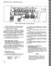
Tune
Coil
R1065:ttl
R1031
Rro32
R10:t4
FM
Coil
Swcco
RtOZl
=?l I
Ccnter
Frcqucncy
Span Attcnualor
\circgir
boild
control
boord
I
I
I
lst
LO
Orivct
lcircuit
board
I
I
556G17
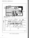
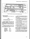
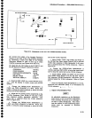
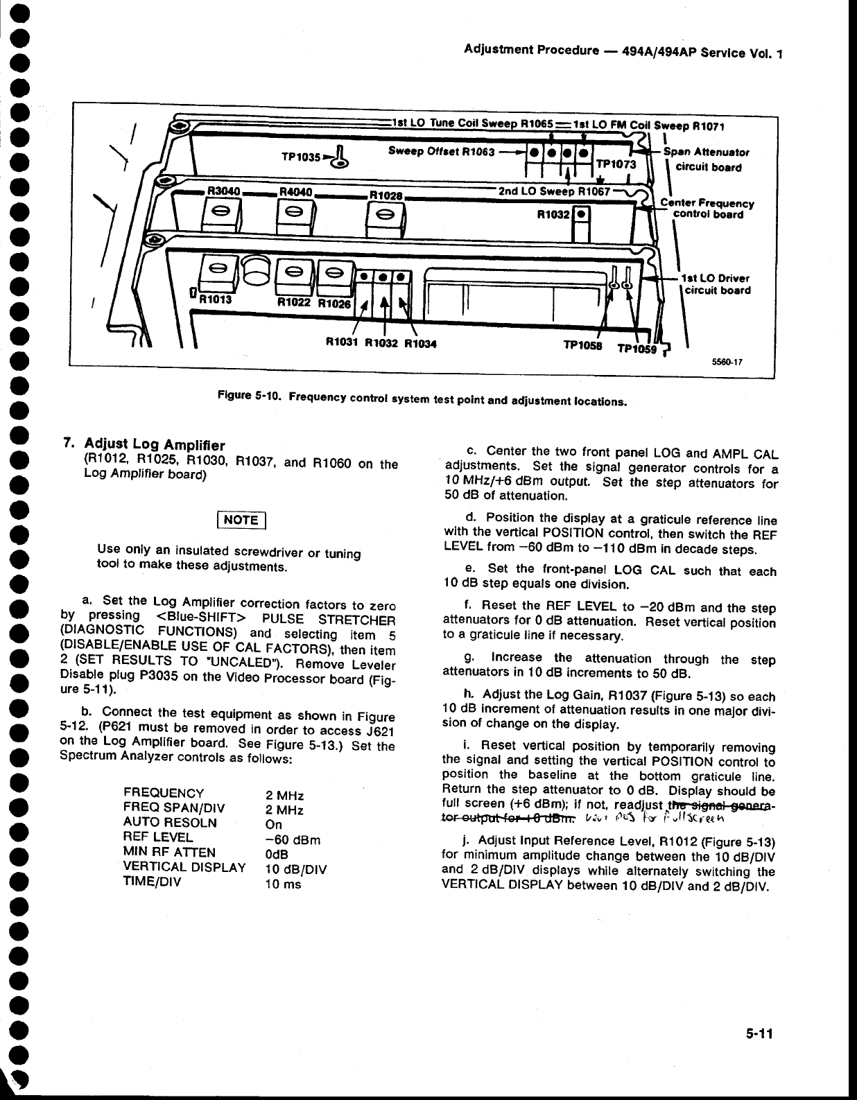
Figure
5'10.
Frequency
contror
system
test
potnt
and
adiustment
rocations.
5-11