


o
o
o
o
o
o
o
o
o
o
o
a
o
o
o
o
o
O
o
o
o
o
o
o
o
o
,
o
o
o
a
o
o
o
a
o
O
o
o
o
o
o
o
o
1.
!{iust
Low
Vottage
power
Suppty
(R6028
and
R6061
on
the
power
Su'pljly
board)
This
high-efficiency
power
supply
uses
an
internal
oscillator
with
a
frequency
of
66
i<fiz.
The
frequency
adjustment
is
normally
-required
only
after
replacin!
oscillator
components;
therefore,
pari
t
is
the
normal
adjustment
and
check
procedure,
part
ll of
this
step
should
only
be required
after
repair
of
the assembly.
Since
the
Spectrum
Analyer
uses
a
high
efficiency
power
supply,
with
the
primjry
ground
potential
different
from
chassis
oi
earth ground,
an
isolation
transform€r
should
be
used
between
the
power
source
and
the
Spectrum
Analyzer
power
input
receptacle.
The
transformer
must
have
a
three-wire
input
and
output
connector
with
ground
throug.h
the
input
and
output.
n
tumper
should
also
be
connected
between
itre
pri-
mary ground
side
to chassis
qround
(emitter
of
e2061
and
the
ground
terminal
of
the
input
fitter
FL301.)
lf
the
power
supply
is
separated
from
the
instrument
and
operated
on
the
bench,
hazardous
potentials
exist
within
the
supply
for
several
seconds
after power
is
discon_
nected.
This
is
due
to
the
slow
discharge
of
capacitors
C6101
and
C6111.
A
retaxl_
tion osciilator
tights
Ds5112
(next
to
c6111)
when
the
potential
exceeds
g0
V.
Part
l:
Check
and
Adjust
Low
Voltages
a.
Connect
a
voltage-variable
transformer
in
,ine
with
the
Spectrum
Analyzer
power
input
and
set
the
transformer
for
l17Vac.
Remove
the cover
over
the
Z-Axis
and
Sweep
boards.
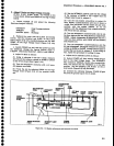
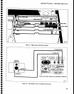
b. Monitor
the
+15
V
test
point
on
the
Z_Axis
board
(Figure
5-1b)
with
a
vottmeter
(DVM).
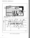
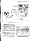
c.
Remove
the
power
Supply
cover
screw
located
below
the
'10
MHz
lF
OUTPUT
jack
on
the rear
panel
(see
Figure
5-1a).
This
wilt
provide
access
to the
+5
V
Reference
adjustment,
R6O2g.
d.
Adjust
R6028
for
+15
V
on
the
vottmeter.
R602g
is
accessed
by
inserting
a
narrow_bit
screwdriver
through
the
screw
hole
that
was
removed
in
part
c of
this
step.
Adjustment
Procedure
-
494A/4g4Ap
Service
Vol.
1
^
e.
Vary
the input
voltage
from
90
Vac
to 132
Vac.
Check
that
the
+1S
V supply
remains
regulated,
and
input
power
does not
exceed
210
W.
f.
Check
the other
supply
voltages
at
the
test
points
indicated
in
Figure
5-.1b, against
tolerances
lisied
in
Table
5-2.
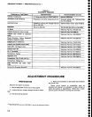
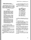
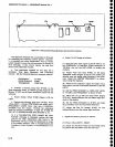
Table
5-2
POWER
SUPPLY
TOLERANCES
S.
Remove
the
voltage-variable
transformer
and
reconnect
the
Spectrum
Analyzer
directly
to
the
power
source.
Part
lt
Adjust
Oscillator
Frequency
a,
Remove
the
power
Supply
module,
as
described
in
the Maintenance
section,
then
remove
the
power
Supply module
cover
and
disconnect
pg045.
b.
Plug
the
power
cord
into
the
power
input
recep_
tacle
and
connect
it
to
a suitable
power
source
(1
1S
Vac
or
230
Vac,
depending
on
the
position
of
the L|NE
SELECTOR
SWTTCH).
c. Use
a
plastic
or
insulated
tuning
tool or
equivalent,
to insert
between
the
two
on/off
power
switches (3300)
to close
these switches
(Figure
5-1a).
d,
Connect
a
test oscilloscope
probe,
with
a
deflection
sensitivity
of
5
V/div
and
sweep
rate
of
10ps/div
to TP6053 (Figure
5-1a).
Note
th€ amplitude
of
the
output
waveform,
of
the
oscillator
U60S9, is
approximately
10 V,
e.
Adjust
R6061
{Osciilator
Freq
Adj)
for a
waveform period
of
15
ps
(66
kHz).
f,
Reconnect
P3045,
replace
the
power
Supply
module
cover,
and
re-install
the
module
on
the Spec-
trum Analyzer.
+8.92
V
to +10.1
V
-4.96
V
to
-5.0S
V
-7
V
to
-8.5
v
-14.84
V
to
-15.16
V
+4.73
V
to +5.29
V
+16.81
V
to +18.6
V
+95
V
to +105
V
+280
V
to +310
V
5-3