Mafntenance
-
494A1494Ap
Servtce
Vot.
1
Input
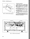
c1045
c2047
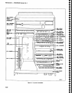
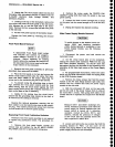
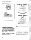
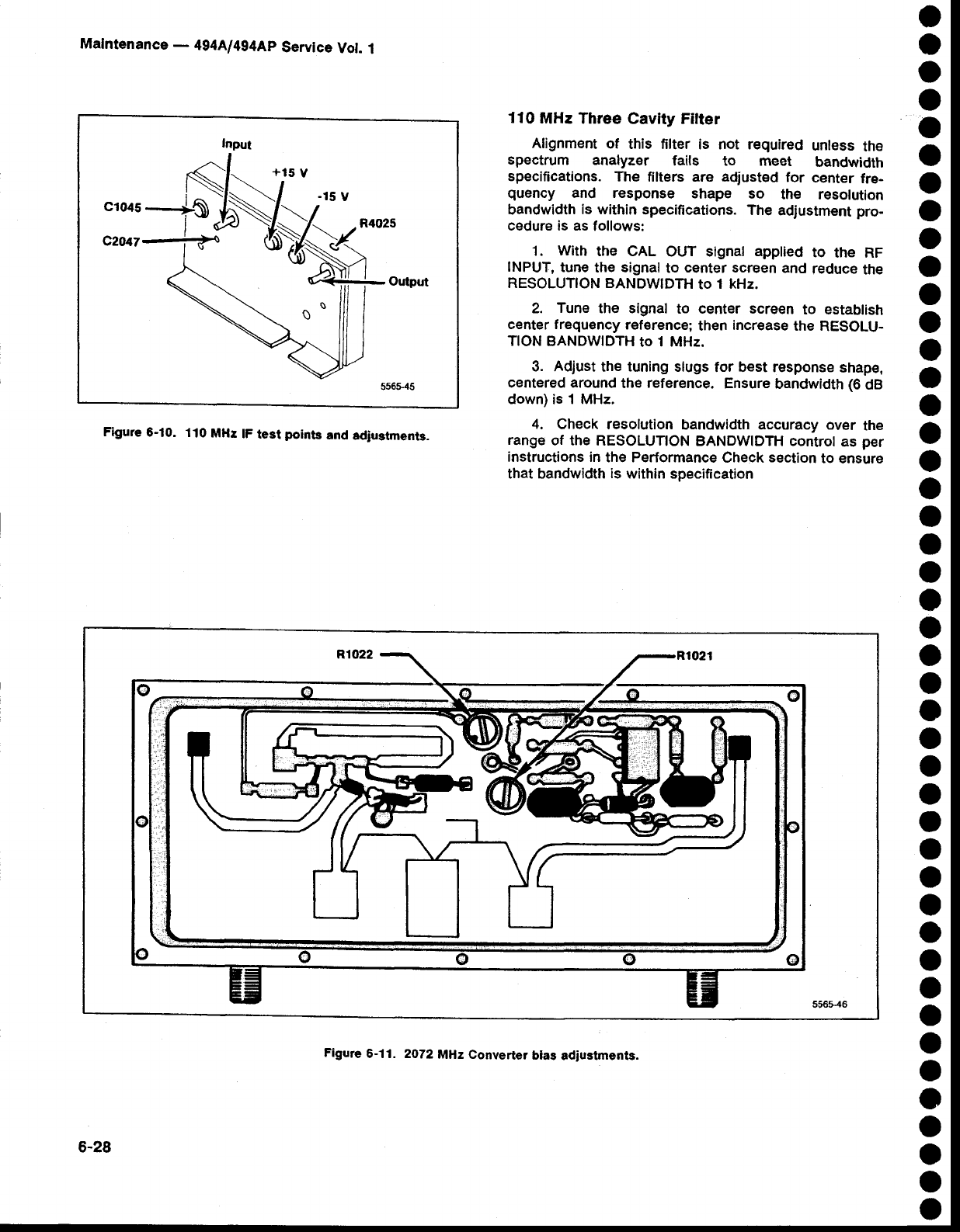
Flgure
6-10.
110
MHz
lF
test
poinb
and
adiuetmenb.
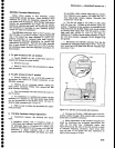
110
MHz Three
Cavity Filter
Alignment
of
this filter
is not required
unless
the
spectrum
analyzer
fails to meet
bandwidth
specifications.
The
filters are adiust€d
for
center
fre-
quency
and response
shape
so
the resolution
bandwidth
is within
specifications.
The
adjustment pro-
cedure is as
follows:
1.
With
the cAL
ouT signat
apptied
to
the RF
INPUT,
tune
the signal
to
center screen
and
reduce
the
RESOLUTION BANDWIDfi
to
1 kHz.
2.
Tune
the signal
to center screen
to establish
center frequency
reference;
then
increase
the
RESOLU-
TION
BANDWIDTH
to
1 MHz.
3. Adjust
the
tuning
slugs
for best response
shape,
centered around
the
reference.
Ensure
bandwidth
(6
dB
down)
is
1 MHz.
4.
Check resolution
bandwidth accuracy over
the
range
of the RESoLUTIoN
BANDWIDTH controt
as
per
instructions in
the Performance
Check
section
to ensure
that bandwidth
is
within specifieation
o
o
o
O
o
o
a
o
o
o
o
o
o
o
o
a
o
O
o
o
o
o
o
o
o
o
a
o
o
o
O
o
o
o
o
O
o
o
o
o
o
o
o
o
6-28
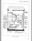
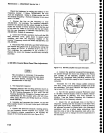
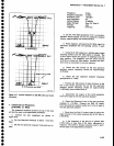
Figure
6-11. 2O72
MHz Converter
blas
adiustments.


